Download
1 / 129
1.59k likes | 2.14k Views
Damage Mechanisms Affecting Fixed Equipment in the Refining Industry. Temper Embrittlement. Description of Damage

E N D
Damage Mechanisms Affecting Fixed Equipment in the Refining Industry
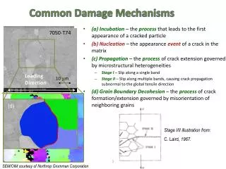
Temper Embrittlement • Description of Damage • Temper embrittlement is the reduction in toughness due to a metallurgical change that occur in some low alloy steels as a result of long-term exposure in the temperature range about 650° F to 1100° F (343° C to 593° C) • This change causes an upward shift in the ductile-to-brittle transition temperature as measured by Charpy impact testing • This phenomenon is related to to the concentration of low-melting point elements (P, Sb, Sn, and S) in the grain boundaries, the crack path is intergranular.
Temper Embrittlement • Affected Materials • Primarily 2.25Cr-1Mo low alloy steel, 3Cr-1Mo (to a lesser extent), and the high-strength low alloy Cr-Mo-V rotor steels • Older generation 2.25Cr-1Mo materials manufactured prior to 1972 may be particularly susceptible. Some high strength low alloy steels are also susceptible • The C-0.5Mo and 1.25Cr-1Mo alloy steels are not significantly affected by temper embrittlement.
Temper Embrittlement • Critical Factors • Alloy steel composition, thermal history, metal temperature and exposure time • Susceptibility to temper embrittlement is largely determined by the presence of the alloying elements manganese and silicon, and tramp elements phosphorus, tin, antimony and arsenic • Temper embrittlement of 2.25Cr-1Mo steels develops more quickly at 900° F (482°C) than in the 800°F (440°C) • Some embrittlement can occur during fabrication heat treatment • This form of damage will significantly reduce the structural integrity of a component containing a crack-like flaw.
Temper Embrittlement • Affected Units or Equipment • Temper emrittlement occurs in a variety of process units after long therm exposure to temperatures above 650°F (343°C) • Equipment susceptible to temper embrittlement is most often found in hydroprocessing units, particularly reactors, hot feet/effluent exchanger components, and hot HP separators. • Welds in these alloys are often more susceptible than the base metal and should be evaluated.
Temper Embrittlement • Appearance of Morphology of Damage • Temper embrittlement is a metallurgical change that is not readily apparent and can be evaluated through impact testing • Temper embrittlement can be identified by an upward shift in the ductile-to-brittle transition temperature measured in a Charpy V-notch impact test, as compared to the non-embrittled or de-embrittled material. (Fig. 4-5) Figure 4-5 - Plot of CVN toughness as a function of temperature showing a shift inthe 40-ft-lbtransition temperature
Temper Embrittlement • Prevention/migration • Cannot be prevented if the material contains critical levels of the embrittling impurity elements and is exposure in the embrittling temperature range • To minimize the possibility of brittle fracture during start-up and shutdown, is used a pressurization sequence to limit system pressure to about 25% of the maximum design pressure for temperatures below a MPT • MPT‘s generally range from 350°F(171°C) for the earliest, most highly temper embrittled steels, down to 150°F (38°C) or lower for newer, temper embrittlement resistant steel • If weld repairs are required, the effects of temper embrittlement can be temporarily reversed by heating at 1150°F (620°C) for 2 hours per 1 inch of thickness, and rapidly cooling to room temperature
Temper Embrittlement • New Materials • The best way to minimize the like hood and extend of temper embrittlement is to limit the acceptance levels of manganese, silicon, phosphorus, tin, antimony, and arsenic in the base metal • A common way to minimize temper embrittlement is to limit the „J*“ factor for base metal and the „X“ factor for weld metal, based on material composition as follows: J* = (Si + Mn)(P + Sn)104 X = (10P + 5Sb + 4Sn + As)/100 • Typical J* and X factors used for 2.25 Cr steel are 100 and 15, respectively
Temper Embrittlement • Inspection and Monitoring • A common method of monitoring is to install blocs of original heats of the alloy steel material inside the reactor • Samples are periodically removed for impact testing • Process condition should be monitored to ensure that a proper pressurization sequence is followed to help prevent brittle fracture due to temper embrittlement
Brittle Fracture • Description of Damage • Brittle fracture is the sudden rapid fracture under stress where the material exhibits little or no evidence of ductility or plastic deformation • Affected materials • Carbon steel and low alloy steel are prime concern, particularly older steel • 400 series SS are also susceptible
Brittle Fracture • Critical Factors • When the critical combination of 3 factors is reached, brittle fracture can occur: • The materials‘ fracture toughness (resistance to crack like flaws) as measured in a Charpy impact test • The size, shape and stress concentration effect of a flaw • The amount of residual and applied stresses on the flaw • Susceptibility to brittle fracture may be increased by the presence of embrittling phases • Steel cleanlines and grain size have a significant influence on thoughness and resistance to brittle fracture • Thicker material section also have a lower resistance to brittle fracture • Brittle fracture occurs only at temperature below the Charpy impact transition temperature, the point at which the toughness of the material drops off sharply
Brittle Fracture • Affected Units or Equipment • Equipment manufactured to the ASME Boiler and Pressure Vessel Code, Section VIII, Division 1, prior to the December 1987 Addena, were made with limited restriction on notch toughness for vessels operating on cold temperatures • Equipment made to the same code after this date were subject to the requirements of UCS 66 • Most processes run at elevated temperature so the main concern is for brittle fracture during start-up, shutdown or hydrogen/thickness testing • Brittle fracture can also occur during an autorefrigeration even in units processing light hydrocarbons such as methane, ethane/ethylene, propane/propylene or butane • Brittle fracture can occur during ambient temperature hydrotesting due to high stresses and low toughness at the testing temperature
Brittle Fracture • Appearance or Morphology of Damage • Crack will typically be straight, non-branchng, and largely devoid of any associated plastic deformation (FIG 4-6 to FIG 4-7) • Microscopicaly, the fracture surface will be composed largely of cleveage, with limited intergranular cracking and vey little micro void coalescence
Figure 4-6 - 20-inch carbon steel pipeline that failed during hydrotest at gouges on the O.D. • Figure 4-7 - Close-up photograph showing the gouges and the fracture origin (arrow) in one of thegouges.
Brittle Fracture • Prevention/Mitigation • For new equipment is best prevent by using materials specifically designed for low temperature operation including upset and autorefrigeration events. • Brittle fracture is an „event“ driven damage mechanism • Preventative measures to minimize the potential for brittle fracture in existing equipment are limited to controlling the operating condition, minimizing pressure at ambient temperatures during startup and shutdown, and periodic inspection at high stress location • Some reduction in the likehood of a brittle fracture may be achieved by: • Performing a post weld heat treatment (PWHT) on the vessel if it was not originally done during manufacturing • Perform a „warm“ pre stress hydrotest followed by a lower temperature hydrotest to extend the Minimum Safe Operating temperature envelope
Thermal Fatigue • Description of Damage • Thermal fatigue is the result of cyclic stresses caused by variations in temperature. • Damage is in the form of cracking that may occur anywhere in a metallic component where relative movement or differential expansion is constrained, particularly under repeated thermal cycling • Affected Materials • All material of construction
Thermal Fatigue • Critical Factors • Key factors-magnitude of the temperature swing and the frequency (number of cycles) • Time to failure is a function of the magnitude of the stress and the number of cycles and decreases with increasing stress and increasing cycles • Damage is also promoted by rapid changes in surface temperature that result in thermal gradient • Notches and sharp corners and other stress concentrations may serve as initiation sites
Thermal Fatigue • Affected Units or Equipment • Mix points of hot and cold streams • Coke drum shells (coke drum skirts where stresses are promoted by a variation in temperature between the drum and skirt) • In steam generating equipment, the most common locations are the rigid attachments between neighboring tubes in the superheater and reheater. • Tubes in the high temperature superheater or reheater that penetrate trough the cooler waterwall tubes may crack at the header connection if the tube is not sufficiently flexible • Steam actuated soot blowers may cause thermal fatigue damage if the first steam existing the soot blower nozzle contains condensate
Figure 4-11 - Thermal fatigue cracks on the inside of a heavy wall SS pipe downstream of a cooler H2 injection into a hot hydrocarbon line • Figure 4-12 - Bulging in a skirt of a Coke Drum
Figure 4-13 - Thermal fatigue cracking associated with bulged skirt shown in Figure 4-12
Thermal Fatigue • Appearance or Morphology of Damage • Thermal fatigue cracks usually initiate on the surface of the component • Thermal fatigue cracks propagate transverse to the stress and they are usually dager-shaped, transgranular, and oxide filled • In steam generating equipment, cracks usually follow the toe of the filled weld, as the change in section thickness creates a stress raiser • Water in soot blowers may lead to a crazing pattern. The predominant cracks will be circumferential and the minor cracks will be axial
Figure 4-15 - Older cracks fill with oxide, may stop and restart (note jog part way along the crack), and do not necessarily require a change in section thickness to initiate the crack. mag. 100x, etched • Figure 4-14 - In a carbon steel sample, metallographic section through thermal fatigue crack indicates origin (here at the toe of an attachment weld) and shape mag. 50x, etched
Thermal Fatigue • Prevention/mitigation • Best prevent is trough the design and operation to minimize thermal stresses and thermal cycling • Design that incorporate reduction of stress concentrators, blend grinding of weld profiles, and smooth transitions should be used • Controlled rates of heating and cooling during startup and shutdown of equipment can lower stresses • Differential thermal expansion between adjoining components of dissimilar materials should be considered • Design should incorporate sufficient flexibility to accommodate differential expansion • In steam generating equipment, slip spacers should slip and rigid attachment should be avoided • Drain lines should be provided on soot-blowers to prevent condensate in the first portion of the soot blowing cycle In some cases, a liner or sleeve may be installed to prevent a colder liquid from contacting the hotter pressure boundary wall
Thermal Fatigue • Inspection and Monitoring • MT and PT are effective methods of inspection • External SWUT inspection can be used for non-intrusive inspection for internal cracking • Heavy wall reactor internal attachment welds can be inspected using specialized ultrasonic techniques
Erosion/Erosion - Corrosion • Description of Damage • Erosion is the accelerated mechanical removal of surface material as a result of relative movement between, or impact of solid, liquids, vapour or any combination thereof • Erosion-corrosion is a description for the damage that occurs when corrosion contributes to erosion by removing protective films or scales, or by exposing the metal surface to further corrosion under the combined action of erosion and corrosion • Affected materials • All metals, alloys and refractories
Erosion/Erosion - Corrosion • Critical Factors • Metal loss rates depend on the velocity and concentration of impacting medium, the size and hardness of impacting particles, the hardness and corrosion resistance of material subject to erosion, and the angle of impact • Softer alloys that are easily worn from mechanical damage • Increasing hardness of the metal substrate is not always a good indicator of improved resistance to erosion, particularly where corrosion plays a significant role. • For each environment-material combination, there is often a threshold velocity above which impacting objects may produce metal loss • The size, shape, density and hardness of the impacting medium affects the metal loss rate • Increasing the corrosivity of the environment may reduce the stability of protective surface films and increase the susceptibility to metal loss • Factors which contribute to an increase in corrosivity of the environment, such as temperature, pH, etc., can increase susceptibility to metal loss.
Erosion/Erosion - Corrosion • Affected Units or Equipment • All types of equipment exposed to moving fluids and/or catalyst as piping systems, particularly the bends, elbows, tees and reducers; piping systems downstream of letdown valves and block valves etc. (Fig. 4-23, Fig. 4-24, Fig. 4-25) • Erosion can be caused by gas borne catalyst particles or by particles carried by a liquid such as a slurry. In refineries, this form of damage occurs as a result of catalyst movement in FCC reactor/regenerator systems in catalyst handling equipment (valves, cyclones etc) and slurry piping as shown on pictures • Hydroprocessing reactor effluent piping may be subject to erosion-corrosion by ammonium bisulfide
Figure 4-23 - Erosion of a 9Cr coker heater return bend • Figure 4-24 - Cast iron impeller in untreated cooling water after four years ofservice
Figure 4-25 – Close-up of figure 4-24 showing both erosion-corrosion at the vane tips and pitting on the pressure side of the vanes
Erosion/Erosion - Corrosion • Appearance or Morphology of Damage • Erosion and erosion-corrosion are characterized by a localized loss in thickness in the form of pits, grooves, gullies, waves, rounded holes and valleys. • Failures can occur in a relatively short time. • Prevention/Mitigation • Improvements in design involve changes in shape, geometry and materials selection • Improved resistance to erosion is usually achieved through increasing substrate hardness using harder alloys, hard facing or surface-hardening treatments • Erosion-corrosion is best mitigated by using more corrosion-resistant alloys and/or altering the process environment to reduce corrosivity • Heat exchangers utilize impingement plates and occasionally tube ferrules to minimize erosion problems. • Higher molybdenum containing alloys are used for improved resistance to naphthenic acid corrosion
Erosion/Erosion - Corrosion • Inspection and Monitoring • Visual examination of suspected or troublesome areas, as well as UT checks or RT • Specialized corrosion coupons and on-line corrosion monitoring electrical resistance probes (in some applications) • IR scans are used to detect refractory loss on stream. • Related Mechanisms • Specialized terminology has been developed for various forms of erosion and erosion-corrosion in specific environments and/or services. • This terminology includes: cavitation, liquid impingement erosion, fretting etc.
Mechanical Fatigue • Description of Damage • Fatigue cracking is a mechanical form of degradation that occurs when a component is exposed to cyclical stresses for an extended period, often resulting in sudden, unexpected failure. • These stresses can arise from either mechanical loading or thermal cycling and are typically well below the yield strength of the material. • Affected Materials • All engineering alloys are subject to fatigue cracking although the stress levels and number of cycles necessary to cause failure vary by material
Mechanical Fatigue • Critical Factors • Geometry, stress level, number of cycles, and material properties (strength, hardness, microstructure) • Design: Fatigue cracks usually initiate on the surface at notches or stress raisers under cyclic loading • Metallurgical Issues and Microstructure • Carbon Steel and Titanium: These materials exhibit an endurance limit below which fatigue cracking will not occur, regardless of the number of cycles • 300 Series SS, 400 Series SS, aluminium, and most other non-ferrous alloys: • These alloys have a fatigue characteristic that does not exhibit an endurance limit • Maximum cyclical stress amplitude is determined by relating the stress necessary to cause fracture to the desired number of cycles necessary in a component's lifetime – typically 106 to 107 cycles
Mechanical Fatigue • Affected Units or Equipment • Thermal Cycling • Equipment that cycles daily in operation such as coke drums • Equipment that may be auxiliary or on continuous standby but sees intermittent service such as auxiliary boiler • Quench nozzle connections that see significant temperature deltas during operations such as water washing systems • Mechanical Loading • Rotating shafts on centrifugal pumps and compressors that have stress concentrations due to changes in radii and key ways. • Components such as small diameter piping that may see vibration from adjacent equipment and/or wind. • High pressure drop control valves or steam reducing stations can cause serious vibration problems in connected piping.
Mechanical Fatigue • Appearance or Morphology of Damage • The signature mark of a fatigue failure is a „clam shell“ type fingerprint that has concentric rings called „beach marks“ emanating from the crack initiation site (Figure 4-29 and Figure 4-30). This signature pattern results from the „waves“ of crack propagation that occur during every cycle above the threshold loading • Cracks nucleating from a surface stress concentration or defect will typically result in a single „clam shell“ fingerprint (Figure 4-31, Figure 4-32 and Figure 4-33.). • Cracks resulting from cyclical overstress of a component without significant stress concentration will typically result in a fatigue failure with multiple points of nucleation and hence multiple „clam shell“ fingerprints
Figure 4-31 - Fatigue crack in a 16-inch pipe-to-elbow weld in the fill line of crude oil storage tank after 50 years in service • Figure 4-32 - A cross-section through the weld showing the crack location
Figure 4-33 - The surface of the fracture faces of the crack shown in Figure 4-31 and Figure 4-32
Mechanical Fatigue • Prevention / Mitigation • Good design that helps minimize stress concentration of components that are in cyclic service • Select a metal with a design fatigue life sufficient for its intended cyclic service • Allow for a generous radius along edges and corners • Minimize grinding marks, nicks and gouges on the surface of components • Insure good fit up and smooth transitions for welds. Minimize weld defects as these can accelerate fatigue cracking • Remove any burrs or lips caused by machining • Use low stress stamps and marking tools
Mechanical Fatigue • Inspection and Monitoring • NDE techniques such as PT, MT and SWUT can be used to detect fatigue cracks at known areas of stress concentration • VT of small diameter piping to detect oscillation or other cyclical movement that could lead to cracking • Vibration monitoring of rotating equipment to help detect shafts that may be out of balance • In high cycle fatigue, crack initiation can be a majority of the fatigue life making detection difficult • Related Mechanisms • Vibration induced fatigue
Atmospheric Corrosion • Description of Damage • A form of corrosion that occurs from moisture associated with atmospheric conditions. Marine environments and moist polluted industrial environments with airborne contaminants are most severe • Dry rural environments cause very little corrosion • Affected Materials • Carbon steel, low alloy steels and copper alloyed aluminium
Atmospheric Corrosion • Critical Factors: • Physical location (industrial, marine, rural); moisture (humidity), particularly designs that trap moisture or when present in a cooling tower mist; temperature; presence of salts, sulfur compounds and dirt • Corrosion rates increase with temperature up to about 250°F (121°C). Above 250°F (121°C), surfaces are usually too dry for corrosion to occur except under insulation • Chlorides, H2S, fly ash and other airborne contaminates from cooling tower drift, furnace stacks and other equipment accelerate corrosion • Bird turds can also cause accelerated corrosion and unsightly stains
Atmospheric Corrosion • Affected Units or Equipment • Piping and equipment with operating temperatures sufficiently low to allow moisture to be present. • A paint or coating system in poor condition. • Equipment may be susceptible if cycled between ambient and higher or lower operating temperatures. • Equipment shut down or idled for prolonged periods unless properly mothballed. • Tanks and piping are particularly susceptible. Piping that rests on pipe supports is very prone to attack due to water entrapment between the pipe and the support. • Orientation to the prevailing wind and rain can also be a factor. • Piers and docks are very prone to attack. • Bimetallic connections such as copper to aluminum electrical connections
Atmospheric Corrosion • Appearance • The attack will be general or localized, depending upon whether or not the moisture is trapped • If there is no coating or if there is a coating failure, corrosion or loss in thickness can be general • Localized coating failures will tend to promote corrosion • Metal loss may not be visually evident, although normally a distinctive iron oxide (red rust) scale forms • Prevention/Mitigation • Surface preparation and proper coating application are critical for long-term protection in corrosive environments
Atmospheric Corrosion • Inspection and Monitoring • VT and UT are techniques that can be used • Related Mechanisms • Corrosion under insulation
Corrosion Under Insulation (CUI) • Description of Damage • Corrosion of piping, pressure vessels and structural components resulting from water trapped under insulation or fireproofing • Affected Materials • Carbon steel, low alloy steels, 300 Series SS and duplex stainless steels
Corrosion Under Insulation (CUI) • Critical Factors • Design of insulation system, insulation type, temperature, environment • Poor design and/or installations that allow water to become trapped will increase CUI • Corrosion rates increase with increasing metal temperature up to the point where the water evaporates quickly. • Corrosion becomes more severe at metal temperatures between the boiling point 212°F (100°C) and 250°F (121°C) • Cyclic thermal operation or intermittent service • Equipment that operates below the water dewpoint tends to condense water on the metal surface thus providing a wet environment • Plants located in areas with high annual rainfall or warmer, marine locations are more prone to CUI than plants located in cooler, drier, mid-continent locations. • Environments that provide airborne contaminants such as chlorides or SO2
Corrosion Under Insulation (CUI) • Affected Units or Equipment • Carbon and low alloy steels are subject to pitting and loss in thickness. • 300 Series SS, 400 Series SS and duplex SS are subject to pitting and localized corrosion. • 300 Series SS are also subject to Stress Corrosion Cracking (SCC) if chlorides are present, while the duplex SS are less susceptible
Corrosion Under Insulation (CUI) • Affected Units or Equipment • Design Issues • CUI can be found on equipment with damaged insulation, vapor barriers, weatherproofing or mastic, or protrusions through the insulation or at insulation termination points such as flanges • Equipment designed with insulation support rings welded directly to the vessel wall • Piping or equipment with damaged/leaking steam tracing • Localized damage at paint and/or coating systems • Locations where moisture/water will naturally collect before evaporating and improperly terminated fireproofing
Corrosion Under Insulation (CUI) • Appearance or Morphology of Damage • Damage may be highly localized (Figure 4-38 and Figure 4-39) • In some localized cases, the corrosion can appear to be carbuncle type pitting (usually found under afailed paint/coating system) • For 300 Series SS, specifically in older calcium silicate insulation, localized pitting and chloride stress corrosion cracking can occur
Figure 4-38 - CUI of CS level bridle • Figure 4-39 - Profile RT of level bridle in Figure 4-38