Download
1 / 24
240 likes | 381 Views
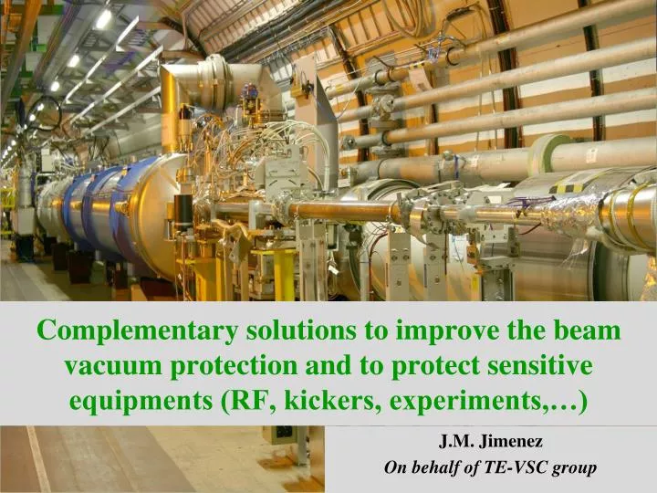
Complementary solutions to improve the beam vacuum protection and to protect sensitive equipments (RF, kickers, experiments,…). J.M. Jimenez On behalf of TE-VSC group. Main Topics. Review of the beam vacuum failure modes Pending issues Mitigation solutions Closing remarks.

E N D
Complementary solutions to improve the beam vacuum protection and to protect sensitive equipments (RF, kickers, experiments,…) J.M. Jimenez On behalf of TE-VSC group
Main Topics • Review of the beam vacuum failure modes • Pending issues • Mitigation solutions • Closing remarks
IntroductionMCI definition MCIeq. 40 kg/s 19th Sept’08 incident CourtesyL. Tavian
Review of the beam vacuum failure modesDirect damage to Beam Vacuum Accidental beam loss making a hole on the beam pipe Short on the cryomagnet coil or lira creating a hole in the cold bore • Expected consequences depend on the type of beam vacuum • Experimental beam vacuum (min. 6 months for repair) • Opening of the Detectors, beam pipe exchange, detector repair… • Beam vacuum at cryogenic temperature e.g. arcs, triplets and SAMs (min. 12 weeks for repair) • Warm-up, magnet exchange, in situ cleaning, cool down… • Beam vacuum operated at ambient temperature (min. 3 weeks for repair) • Mechanical intervention, bake out and NEG activation • Impact onto the beam vacuum depends on the type of damages (ranking) • Contamination by dust, MLI or soot • Dust and MLI could be cleaned in-situ, soot implies the removal of contaminated components • Internal pressurization of the beam vacuum • Could lead to buckling of the bellows and require the exchange of cryomagnets… • Venting to air or to dry helium • Venting to dry helium does not require the warm-up of cryomagnets…
Review of the beam vacuum failure modesBeam Vacuum damaged by collateral effects (1/4) • Beam pipe pressurization resulting from an injection of cold helium • Expected consequences depend on the type of beam vacuum • Beam vacuum operated at ambient temperature (LSS and Experimental areas) • Mechanical intervention, bake out and NEG activation • Experimental beam vacuum • Opening of the Detectors, beam pipe exchange… • Beam vacuum at cryogenic temperature (arcs, triplets and SAMs) • Warm-up, magnet exchange, in situ cleaning, cool down… • Impact onto the beam vacuum depends on the efficiency of compensatory measures decided after the incident of sector 3-4 • Reinforcement of the supports of the cryomagnets with vacuum barriers • Limits the risk of mechanical displacement and damaging of the Plug-in modules (PIMs) and nested bellows • Additional pressure relief valves (or unclamped flanges) • Limit the pressurization level of the insulation vacuum • By-pass at the vacuum barriers (on pumping stations) • Limit the pressurization level of the insulation vacuum
Review of the beam vacuum failure modesBeam Vacuum damaged by collateral effects (2/4) • Reinforcement of the supports of the cryomagnets with vacuum barriers • Limits the risk of mechanical displacement and damaging of the Plug-in modules (PIMs) and nested bellows • Preventing the injection of cold helium and contamination into the beam vacuum
Review of the beam vacuum failure modesBeam Vacuum damaged by collateral effects (3/4) • DN200/160/100 pressure relief valves and/or declamped flanges to limit the pressurization of the insulation vacuum • Limit the pressurization level of the insulation vacuum Without DN200(declamping of existing flanges) DN200 “declamped” configuration DN100 “declamped” configuration Without DN200 DN100 “spring” configuration DN200 “spring” configuration
Review of the beam vacuum failure modesBeam Vacuum damaged by collateral effects (4/4) • By-pass at the vacuum barriers (on pumping stations) • Limit the pressurization level of the insulation vacuum • Implemented on sectors not yet consolidated with DN200 pressure relief valves • Proposal being prepared to extend this configuration to all arcs (2012)
Pending IssuesRF cavities, kickers and Experimental areas (1/4) • Vacuum failure without pressurization • Venting with dry helium without contamination should not be a major issue • Commissioning: several days will be required • Venting with air without contamination will required a bake out for the kickers and a warming up of the SC RF cavities • Bake out/venting followed by commissioning: several weeks • Venting with contamination will impact significantly the performances of these equipments • Removal from the tunnel to be considered • Not enough spare available • Vacuum failure with pressurization • Critical in most of these equipments • Supports in the Experimental areas are not design to stand induced forces • Ceramics, bellows could fail in presence of an internal pressurization • None of these vacuum sectors is equipped with rupture disks
Pending IssuesRF cavities, kickers and Experimental areas (2/4) • Configuration around and on between the kickers does not favor optimum solution • 0.5 m between kickers • Cannot protect one kicker against its neighbor… • 2 m between kickers and Q4D2/Q5 cryomagnets • Cannot protect one kicker against its neighboring cryomagnet… • Can protect kickers from the arc • Not obvious that absolutely required, “damping” effect of NEG coatings and Q6/Q5 cryomagnets
Pending IssuesRF cavities, kickers and Experimental areas (3/4) • Configuration around and on between the cavities does not favor optimum solution • 0.5 m between cavity 2 and 3 • Cannot protect one cavity against its neighbor… • Can protect cavity 1 and 4… • >30 m between kickers and D3 cryomagnets • Can protect the cavities against their neighboring cryomagnets… • Can protect cavities from the arc • Not obvious that it is absolutely required, “damping” effect of NEG coatings and Q6/Q5/D4/D3 cryomagnets
Pending IssuesRF cavities, kickers and Experimental areas (4/4) • Configuration around and on the Experimental areas does not favor optimum solution • Few meters between the “central” beam vacuum sector and Q1 cryomagnets • Cannot protect the Experimental beam vacuum from the triplets… • >50 m between the Experimental beam vacuum and the D2Q4 cryomagnets, • Can protect the Experiments against D2Q4 cryomagnets… • Can protect the Experimental beam vacuum from the arc • Not obvious that absolutely required, “damping” effect NEG coatings and cryomagnets Triplets « Central » beamvacuum sector Triplets
Mitigation solutionsPressure relief valves • New design of DN200/160/100 valves • Opens in case of a slight overpressure an then “recloses” at equilibrium (internal/external) • “Self” positioning to improve tightness reliability • Limits contamination /condensation of huge quantities of air • Water (MLI) and Oxygen (explosion risk) are the most delicate • To be applied to all “declamped” positions (DN100/160/200) • Proposal being studied for all positions (2012)
Mitigation solutionsRupture disks (1/4) • New design of rupture disks • Opens in case of pressurization and then closes off when pressures are at equilibrium • Limits the contamination /condensation of huge quantities of air • Water (MLI) and Oxygen (explosion risk) are the most delicate • Self protected in case of a failure of the disk • Accidental venting is avoided by the viton sealed cap • Less critical design, more adapted to an extended use in the arcs • Limits the buckling of the bellows (PIMs and nested)in case of an internal pressurisation
Mitigation solutionsRupture disks (2/4) Internal pressurization UHV PA
Mitigation solutionsRupture disks (2/4) Accidental rupture of the disk UHV PA
Mitigation solutionsRupture disks (3/4) Max. pressure (quench valve) Adjustedlevelat 10 bars (quench valve)
Mitigation solutionsRupture disks (3/4) Adjustedlevelat 10 bars (quench valve)
Mitigation solutionsRupture disks (4/4) • External pressurization should no longer be a problem • 1.5 bar for consolidated sectors, for an MCI (40 kg/s) • 3.5 bars for the non-consolidated sectors, for an MCI (40 kg/s) • PIMs and Nested bellows have a higher buckling pressure, 3.5 and 5 bars respectively • Internal pressurization is a major issue • If an impact of the beam onto the beam screen / cold bore can not be excluded • Recommends to install additional rupture disks. In case of an MCI, • 200 m of machine could have buckled bellows if each SSS is equipped • 400 m of machine could have buckled bellows if each 1 SSS over 2 is equipped • 600 m of machine could have buckled bellows if each 1 SSS over 3 is equipped • Etc.
Mitigation solutionsFast shutters (1/2) • Prerequisites • Shall not be necessarily leak tight • Shall limit the propagation of the contamination • Shall close within 20-50 ms • Shall not be dangerous for the machine in case beams intercept the sealing plate • Shall use a low-Z material for the sealing plate • Transparent to the beam • Faster since lighter • Spring or pyrotechnic actuator (adapt commercially available actuators) • Requires reliable interlock signals • Beam loss monitors • Pressure gauges or nQPS in the absence of circulating beams • Needs a complete development and validation tests • Being studied in the TE-VSC group • Conceptual design expected by end 2010 • Installation foreseen for 2012
Mitigation solutionsFast shutters (2/2) • Vacuum failure without pressurization • Propagation of the contamination is an issue since the arc is not sectorised • No space left in an interconnection to install a fast shutter… Stilllookingfor ideas…
Mitigation solutionsHalf-shells • Two half-shells in Vetronite or equivalent • Shall protect the bellows (PIMs and nested) in the interconnections • Increase resistance to plasma discharge (high temperature resistance) • Avoid damages induced by the projections of melted metal • Limit the injection of MLI in the Beam Vacuum • Slightly increase the buckling pressure by a “guiding effect” • Shall use insulating material to repulse the plasma/arcing risk • Easy to retrofit during the consolidation of the splices
Closing Remarks • Prerequisites and required time to implement • Half-shells are easy to install and will be coupled with the consolidation of the splices (2012) • Additional rupture disks sounds a good idea • Installed at all extremities of the 4 Experimental areas Needs a venting to dry Neon to equip the central vacuum sector • Will allow to put back into operation, the sector valves… • In the arcs Needs a warm up and can be coupled with the consolidation of the splices • Proposal will be presented to LMC by Automn’10 • Reliability and limitation of collateral damages in case of a membrane failure is being considered (see new design) • Fast-closing valves need a technical development and validation • On going studies, first proposal (conceptual) by end 2010 • Implementation in 2012 • Implementation in the arcs seems difficult
Acknowledgements • Many thanks to all contributors from TE, EN and BE Departments for their contributions and helpful discussions.