Download
1 / 41
410 likes | 468 Views
In system design, decompose the system into smaller subsystems and define project goals. Select strategies for hardware/software, data management, global control flow, access control, and boundary conditions. Result is a model with subsystem decomposition and strategy descriptions. Explore system layers, cohesion, coupling, concurrency, hardware/software mapping, data management, access control, and more. Understand system decomposition, service definition, boundary conditions, and subsystem interfaces. Learn to choose subsystems effectively based on cohesion and coupling. Improve complexity reduction through cohesion and coupling measurements.

E N D
Chapter 6 System Design: Decomposing the system
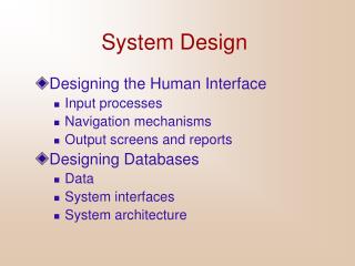
What is system design • Decompose the system into smaller subsystems • Define the design goals of the project • Select strategies for building the system • Hardware/software strategy • Persistent data management strategy • Global control flow • Access control policy • Handling of boundary conditions • The result of system design is a model that includes a subsystem decomposition and a clear description of each of these strategies
1. Design Goals Defi nition T rade-of fs 8. Boundary Conditions Initialization T ermination System Design System Design Failure 2. System Decomposition Layers/Partitions Cohesion/Coupling 7. Software Control Monolithic Event-Driven Threads Conc. Processes 3. Concurrency 6. Global 4. Hardware/ Identification of Threads 5. Data Resource Handling Softwar e Management Mapping Access control Security Persistent Objects Special purpose Files Buy or Build Trade-off Databases Allocation Data structure Connectivity
Overview System Design I (Today) 0. Overview of System Design 1. Subsystem Decomposition System Design II: Addressing Design Goals (next lecture) 2. Design Goals 3. Concurrency 4. Hardware/Software Mapping 5. Persistent Data Management 6. Global Resource Handling and Access Control 7. Software Control 8. Boundary Conditions
How to use the results from the Requirements Analysis for System Design • Nonfunctional requirements => • Activity 1: Design Goals Definition • Functional model => • Activity 2: System decomposition (Selection of subsystems based on functional requirements, cohesion, and coupling) • Object model => • Activity 4: Hardware/software mapping • Activity 5: Persistent data management • Dynamic model => • Activity 3: Concurrency • Activity 6: Global resource handling • Activity 7: Software control • Subsystem Decomposition • Activity 8: Boundary conditions
Section 2. System Decomposition • Subsystem (UML: Package) • Collection of classes, associations, operations, events and constraints that are interrelated • Seed for subsystems: UML Objects and Classes. • (Subsystem) Service: • Group of operations provided by the subsystem • Seed for services: Subsystem use cases • Service is specified by Subsystem interface: • Specifies interaction and information flow from/to subsystem boundaries, but not inside the subsystem. • Should be well-defined and small. • Often called API: Application programmer’s interface, but this term should used during implementation, not during System Design
Services and Subsystem Interfaces • Service: A set of related operations that share a common purpose • Notification subsystem service: • LookupChannel() • SubscribeToChannel() • SendNotice() • UnscubscribeFromChannel() • Services are defined in System Design • Subsystem Interface: Set of fully typed related operations. • Subsystem Interfaces are defined in Object Design • Also called application programmer interface (API)
Definition: Subsystem Interface Object • A Subsystem Interface Object provides a service • This is the set of public methods provided by the subsystem • The Subsystem interface describes all the methods of the subsystem interface object
System as a set of subsystems communicating via a software bus Authoring Modeling Workflow Augmented Reality Inspection Repair Workorder A Subsystem Interface Object publishes the service (= Set of public methods) provided by the subsystem
Choosing Subsystems • Criteria for subsystem selection: Most of the interaction should be within subsystems, rather than across subsystem boundaries (High cohesion). • Does one subsystem always call the other for the service? • Which of the subsystems call each other for service? • Primary Question: • What kind of service is provided by the subsystems (subsystem interface)? • Secondary Question: • Can the subsystems be hierarchically ordered (layers)?
Modeling Authoring Workorder Repair Inspection Augmented Reality Workflow Subsystem Decomposition Example Is this the right Decomposition?
Coupling and Cohesion • Goal: Reduction of complexity while change occurs • Cohesion measures the dependence among classes within a subsystem • High cohesion: The classes in the subsystem perform similar tasks and are related to each other (via associations) • Low cohesion: Lots of miscellaneous and auxiliary classes, no associations • Coupling measures dependencies between subsystems • High coupling: Changes to one subsystem will have high impact on the other subsystem (change of model, massive recompilation, etc.) • Low coupling: A change in one subsystem does not affect any other subsystem • Subsystems should have as maximum cohesion and minimum coupling as possible: • How can we achieve high cohesion? • How can we achieve loose coupling? Our class as a system, graduate/undergraduate as subsystem, group as subsystems
Repair Inspection Authoring Augmented Reality Workflow Modeling A 3-layered Architecture
Partitions and Layers Partitioning and layering are techniques to achieve low coupling. A large system is usually decomposed into subsystems using both, layers and partitions. • Partitions vertically divide a system into several independent (or weakly-coupled) subsystems that provide services on the same level of abstraction. • A layer is a subsystem that provides subsystem services to a higher layers (level of abstraction) • A layer can only depend on lower layers • A layer has no knowledge of higher layers Take our class as an example again. Partitions – groups, layers – classroom infrastructure and classes
Layer 1 Layer 2 Layer 3 Subsystem Decomposition into Layers • Subsystem Decomposition Heuristics: • No more than 7+/-2 subsystems • More subsystems increase cohesion but also complexity (more services) • No more than 4+/-2 layers, use 3 layers (good)
Relationships between Subsystems • Layer relationship • Layer A “Calls” Layer B (runtime) • Layer A “Depends on” Layer B (“make” dependency, compile time) • Partition relationship • The subsystem have mutual but not deep knowledge about each other • Partition A “Calls” partition B and partition B “Calls” partition A
Virtual Machine • Dijkstra: T.H.E. operating system (1965) • A system should be developed by an ordered set of virtual machines, each built in terms of the ones below it. Problem VM1 C1 C1 C1 attr attr attr opr opr opr C1 C1 VM2 attr attr opr opr C1 VM3 C1 attr attr opr opr C1 VM4 attr opr Existing System
Virtual Machine • A virtual machine is an abstraction • It provides a set of attributes and operations. • A virtual machine is a subsystem • It is connected to higher and lower level virtual machines by "provides services for" associations. • Virtual machines can implement two types of software architecture • Open and closed architectures.
C1 C1 C1 C1 C1 C1 C1 C1 C1 VM1 attr attr attr attr attr attr attr attr attr op op op op op op op op op VM2 VM3 VM4 Closed Architecture (Opaque Layering) • Any layer can only invoke operations from the immediate layer below • Design goal: High maintainability, flexibility
C1 C1 C1 C1 C1 C1 C1 C1 C1 attr attr attr attr attr attr attr attr attr op op op op op op op op op Open Architecture (Transparent Layering) • Any layer can invoke operations from any layers below • Design goal: Runtime efficiency VM1 VM2 VM3 VM4
Properties of Layered Systems • Layered systems are hierarchical. They are desirable because hierarchy reduces complexity (by low coupling). • Closed architectures are more portable. • Open architectures are more efficient. • If a subsystem is a layer, it is often called a virtual machine.
Software Architectural Styles • Subsystem decomposition • Identification of subsystems, services, and their relationship to each other. • Specification of the system decomposition is critical. • Patterns for software architecture • Repository • Client/Server • Peer-To-Peer • Model/View/Controller • Pipes and Filters
Repository Subsystem createData() setData() getData() searchData() Repository Architectural Style (Blackboard Architecture, Hearsay II Speech Recognition System) • Subsystems access and modify data from a single data structure • Subsystems are loosely coupled (interact only through the repository) • Control flow is dictated by central repository (triggers) or by the subsystems (locks, synchronization primitives)
SemanticAnalyzer Repository SymbolTable ParseTree SourceLevelDebugger Examples of Repository Architectural Style Compiler • Hearsay II speech understanding system (“Blackboard architecture”) • Database Management Systems • Modern Compilers SyntacticAnalyzer Optimizer CodeGenerator LexicalAnalyzer SyntacticEditor
initiator Controller 1 repository * Model 1 notifier subscriber View * Model/View/Controller • Subsystems are classified into 3 different types • Model subsystem: Responsible for application domain knowledge • View subsystem: Responsible for displaying application domain objects to the user • Controller subsystem: Responsible for sequence of interactions with the user and notifying views of changes in the model. • MVC is a special case of a repository architecture: • Model subsystem implements the central datastructure, the Controller subsystem explicitly dictate the control flow
Example of a File System Based on the MVC Architectural Style
2.User types new filename 3. Request name change in model :Controller 1. Views subscribe to event :Model 5. Updated views 4. Notify subscribers :InfoView :FolderView Sequence of Events (Collaborations) Another Example: A multi-user simulation game system
Client/Server Architectural Style • One or many servers provides services to instances of subsystems, called clients. • Client calls on the server, which performs some service and returns the result • Client knows the interface of the server (its service) • Server does not need to know the interface of the client • Response in general immediately • Users interact only with the client
Client/Server Architectural Style • Often used in database systems: • Front-end: User application (client) • Back end: Database access and manipulation (server) • Functions performed by client: • Customized user interface • Front-end processing of data • Initiation of server remote procedure calls • Access to database server across the network • Functions performed by the database server: • Centralized data management • Data integrity and database consistency • Database security • Concurrent operations (multiple user access) • Centralized processing (for example archiving)
Advantages for Client/Server Systems • Service Portability • Server can be installed on a variety of machines and operating systems and functions in a variety of networking environments • Transparency, Location-Transparency • The server might itself be distributed (why?), but should provide a single "logical" service to the user • Performance • Client should be customized for interactive display-intensive tasks • Server should provide CPU-intensive operations • Scalability • Server should have spare capacity to handle larger number of clients • Flexibility • The system should be usable for a variety of user interfaces and end devices (eg. WAP Handy, wearable computer, desktop) • Reliability • System should survive node or communication link problems
Problems with Client/Server Architectural Styles • Layered systems do not provide peer-to-peer communication • Peer-to-peer communication is often needed • Example: Database receives queries from application but also sends notifications to application when data have changed
Peer-to-Peer Architectural Style • Generalization of Client/Server Architecture • Clients can be servers and servers can be clients • More difficult because of possibility of deadlocks
Peer Client Server
Three-tier • Three layers • The interface layer includes all boundary objects that deal with the user, including windows, forms, web pages • The application logic layer includes all control and entity objects, realizing the processing, rule checking, and notification required by the application • The storage layer realizes the storage, retrieval, and query of persist objects
Three-tier Enable different user interfaces for the same application logic Interface Form Application logic Connection Storage Query The storage can be shared by different applications
Example of a Layered Architectural Style Layer Application • ISO’s OSI Reference Model • ISO = International Standard Organization • OSI = Open System Interconnection • Reference model defines 7 layers of network protocols and strict methods of communication between the layers. • Closed software architecture Presentation Session Level of abstraction Transport Network DataLink Physical
OSI model Packages and their Responsibility • The Physical layer represents the hardware interface to the net-work. It allows to send() and receivebits over a channel. • The Datalink layerallows to send and receive frames without error using the services from the Physical layer. • The Network layer is responsible for that the data are reliably transmitted and routed within a network. • The Transport layeris responsible for reliably transmitting from end to end. (This is the interface seen by Unix programmers when transmitting over TCP/IP sockets) • The Session layer is responsible for initializing a connection, including authentication. • The Presentation layer performs data transformation services, such as byte swapping and encryption • The Application layer is the system you are designing (unless you build a protocol stack). The application layer is often layered itself.
Another View at the ISO Model • A closed software architecture • Each layer is a UML package containing a set of objects
Application Object Presentation CORBA Session Transport Socket TCP/IP Network DataLink Physical Ethernet Wire Middleware Allows Focus On The Application Layer
Middleware General-purpose software, defined by an API, that facilitates application elements to interoperate at a logical level, be distributed across multiple systems, or ported to another platform, despite differences in underlying communication protocols, operating systems, or other basic services.
Summary • System Design • Reduces the gap between requirements and the (virtual) machine • Decomposes the overall system into manageable parts • Subsystem Decomposition • Results into a set of loosely dependent parts which make up the system • Define and Address Design Goals • Describes and prioritizes the qualities that are important for the system • Defines the value system against which options are evaluated • Next class