Download
1 / 49
490 likes | 501 Views
Lecture 4: Pipeline Complications: Data and Control Hazards. Professor Alvin R. Lebeck Computer Science 220 Fall 2001. Administrative. Homework #1 Due Tuesday, September 11 Start Reading Chapter 4 Projects. ALUop. ALU Control. ALUctr. 3. RegDst. func. op. 3. Main Control.

E N D
Lecture 4: Pipeline Complications:Data and Control Hazards Professor Alvin R. Lebeck Computer Science 220 Fall 2001
Administrative • Homework #1 Due Tuesday, September 11 • Start Reading Chapter 4 • Projects CPS 220
ALUop ALU Control ALUctr 3 RegDst func op 3 Main Control Instr<5:0> 6 ALUSrc 6 : Instr<31:26> Instruction<31:0> Branch Instruction Fetch Unit Jump <0:15> <21:25> <16:20> <11:15> Rd Rt Clk RegDst 1 0 Mux Rt Rs Rd Imm16 Rs Rt RegWr ALUctr 5 5 5 MemtoReg busA Zero MemWr Rw Ra Rb busW 32 32 32-bit Registers 0 ALU 32 busB 32 0 Clk Mux 32 Mux 32 1 WrEn Adr 1 Data In 32 Extender Data Memory imm16 32 16 Instr<15:0> Clk ALUSrc ExtOp Review: A Single Cycle Processor CPS 220
6 PM 7 8 9 Time 30 40 40 40 40 20 T a s k O r d e r A B C D Review: Pipelining Lessons • Pipelining doesn’t help latency of single task, it helps throughput of entire workload • Pipeline rate limited by slowest pipeline stage • Multiple tasks operating simultaneously • Potential speedup = Number pipe stages • Unbalanced lengths of pipe stages reduces speedup • Time to “fill” pipeline and time to “drain” it reduces speedup CPS 220
Cycle 1 Cycle 2 Cycle 3 Cycle 4 Cycle 5 Load Ifetch Reg/Dec Exec Mem WrB Review: The Five Stages of a Load • Ifetch: Instruction Fetch • Fetch the instruction from the Instruction Memory • Reg/Dec: Registers Fetch and Instruction Decode • Exec: Calculate the memory address • Mem: Read the data from the Data Memory • WrB: Write the data back to the register file
Cycle 1 Cycle 2 Cycle 3 Cycle 4 Cycle 5 Cycle 6 Cycle 7 1st lw Ifetch Reg/Dec Exec Mem WrB 2nd lw Ifetch Reg/Dec Exec Mem WrB 3rd lw Ifetch Reg/Dec Exec Mem WrB Review: Pipelining the Load Instruction • The five independent pipeline stages are: • Read Next Instruction: The Ifetch stage. • Decode Instruction and fetch register values: The Reg/Decstage • Execute the operation: The Exec stage. • Access Data-Memory: The Mem stage. • Write Data to Destination Register: The WrB stage • One instruction enters the pipeline every cycle • One instruction comes out of the pipeline (completed) every cycle • The “Effective” Cycles per Instruction (CPI) is 1; ~1/5 cycle time Clock
4 1 2 3 5 Mem R-type Ifetch Reg/Dec Exec Wr Ifetch Reg/Dec Exec Mem WrB Ifetch Reg/Dec Exec Mem WrB Ifetch Reg/Dec Exec Mem WrB Ifetch Reg/Dec Exec Mem WrB Ifetch Reg/Dec Exec Mem WrB Review: Delay R-type’s Write by One Cycle • Delay R-type’s register write by one cycle: • Now R-type instructions also use Reg File’s write port at Stage 5 • Mem stage is a NO-OPstage: nothing is being done. Effective CPI? Cycle 1 Cycle 2 Cycle 3 Cycle 4 Cycle 5 Cycle 6 Cycle 7 Cycle 8 Cycle 9 Clock R-type R-type Load R-type R-type
Clk Ifetch Reg/Dec Exec Mem WrB ExtOp ALUOp Branch RegWr 1 0 PC+4 PC+4 PC Imm16 PC+4 Imm16 Data Mem Rs Zero busA A Ra busB Exec Unit EX Unit RA Do Rb IF_Unit ID/Ex Register IF/ID Register Ex/Mem Register Mem/Wr Register 1 Rt WA RFile Mux Di Rw Di Rt 0 0 I Rd 1 ALUSrc RegDst MemWr MemtoReg Review: A Pipelined Datapath
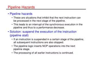
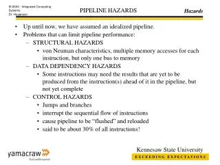
Its Not That Easy for Computers • What could go wrong? • Limits to pipelining: Hazards prevent next instruction from executing during its designated clock cycle • Structural hazards: HW cannot support this combination of instructions • Data hazards: Instruction depends on result of prior instruction still in the pipeline • Control hazards: Pipelining of branches & other instructions CPS 220
Speed Up Equation for Pipelining Speedup from pipelining = Ave Instr Time unpipelined Ave Instr Time pipelined = CPIunpipelined x Clock Cycleunpipelined CPIpipelined x Clock Cyclepipelined = CPIunpipelined Clock Cycleunpipelined CPIpipelined Clock Cyclepipelined Ideal CPI = CPIunpipelined/Pipeline depth Speedup = Ideal CPI x Pipeline depth Clock Cycleunpipelined CPIpipelined Clock Cyclepipelined x x CPS 220
Speed Up Equation for Pipelining CPIpipelined = Ideal CPI + Pipeline stall clock cycles per instr Speedup = Ideal CPI x Pipeline depth Clock Cycleunpipelined Ideal CPI + Pipeline stall CPI Clock Cyclepipelined Speedup = Pipeline depth Clock Cycleunpipelined 1 + Pipeline stall CPI Clock Cyclepipelined x x CPS 220
Example: Dual-port vs. Single-port • Machine A: Dual ported memory • Machine B: Single ported memory, but its pipelined implementation has a 1.05 times faster clock rate • Ideal CPI = 1 for both • Loads are 40% of instructions executed • SpeedUpA = Pipeline Depth/(1 + 0) x (clockunpipe/clockpipe) • = Pipeline Depth • SpeedUpB = Pipeline Depth/(1 + 0.4 x 1) x (clockunpipe/(clockunpipe / 1.05) • = (Pipeline Depth/1.4) x 1.05 • = 0.75 x Pipeline Depth • SpeedUpA / SpeedUpB = Pipeline Depth/(0.75 x Pipeline Depth) = 1.33 • Machine A is 1.33 times faster CPS 220
Three Generic Data Hazards • InstrI followed by InstrJ • Read After Write (RAW)InstrJ tries to read operand before InstrI writes it CPS 220
Three Generic Data Hazards • InstrI followed by InstrJ • Write After Read (WAR)InstrJ tries to write operand before InstrI reads it • Can’t happen in DLX 5 stage pipeline because: • All instructions take 5 stages, • Reads are always in stage 2, and • Writes are always in stage 5 CPS 220
Three Generic Data Hazards • InstrI followed by InstrJ • Write After Write (WAW)InstrJ tries to write operand before InstrI writes it • Leaves wrong result ( InstrI not InstrJ) • Can’t happen in DLX 5 stage pipeline because: • All instructions take 5 stages, and • Writes are always in stage 5 • Will see WAR and WAW in later more complicated pipes CPS 220
Ifetch Reg/Dec Exec Mem WrB Ifetch Reg/Dec Exec Mem WrB Ifetch Reg/Dec Exec Mem WrB Ifetch Reg/Dec Exec Mem WrB Ifetch Reg/Dec Exec Mem WrB Data Hazards • We must deal with instruction dependencies. • Example: sub$2, $1, $3 and $12, $2, $5# $12 depends on the result in $2 or $13, $6, $2 # but $2 is updated 3 clock add $14, $2, $2 # cycles later. sw $15, 100($2)# We have a problem!! Data Hazard Cycle 1 Cycle 2 Cycle 3 Cycle 4 Cycle 5 Cycle 6 Cycle 7 Cycle 8 Clock 0: sub 4: and 8: or 12: add 16: sw
Cycle 1 Cycle 2 Cycle 3 Cycle 4 Cycle 5 Cycle 6 Cycle 7 Cycle 8 Clock I0: Load Ifetch Reg/Dec Exec Mem Wr Plus 1 Wr Ifetch Reg/Dec Exec Mem Plus 2 Ifetch Reg/Dec Exec Mem Wr Plus 3 Ifetch Reg/Dec Exec Mem Wr Plus 4 Ifetch Reg/Dec Exec Mem Wr RAW Data Hazard for Load • Load is fetched during Cycle 1: • The data is NOT written into the Reg File until the end of Cycle 5 • We cannot read this value from the Reg File until Cycle 6 • 3-instruction delay before the load takes effect • This is a Data Hazard: • Register forwarding reduces the load delay to ONEinstruction • It is not possible to entirely eliminate the load Data Hazard!
Insert NOOP Here Stall2 Stall1 Stall0 How? ExtOp ALUOp Branch RegWr 1 0 PC+4 PC+4 PC Imm16 PC+4 Imm16 Data Mem Rs Zero busA A Ra busB Exec Unit EX Unit RA Do Rb IF_Unit Mem/Wr Register IF/ID Register ID/Ex Register Ex/Mem Register 1 Rt WA RFile Mux Di Rw Di Rt 0 0 I Rd 1 ALUSrc RegDst MemWr MemtoReg Dealing with the Load Data Hazard • There are two ways to deal with the load data hazard: • Insert a NOOP bubble into the data path. • Use Delayed load semantic (see a next slide)
Delayed Load • Load instructions are defined such that immediate successor instruction will not read result of load. BAD ld r1, 8(r2) sub r3, r1, r3 add r2, r2, 4 OK ld r1, 8(r2) add r2, r2, 4 sub r3, r1, r3
Software Scheduling to Avoid Load Hazards Try producing fast code for a = b + c; d = e – f; assuming a, b, c, d ,e, and f in memory. Slow code: LW Rb,b LW Rc,c ADD Ra,Rb,Rc SW a,Ra LW Re,e LW Rf,f SUB Rd,Re,Rf SW d,Rd Fast code: LW Rb,b LW Rc,c LW Re,e ADD Ra,Rb,Rc LW Rf,f SW a,Ra SUB Rd,Re,Rf SW d,Rd CPS 220
Compiler Avoiding Load Stalls CPS 220
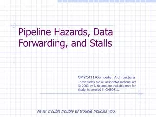
Review: Data Hazards • RAW • only one that can occur in DLX pipeline • WAR • WAW • Data Forwarding (Register Bypassing) • send data from one stage to another bypassing the register file • Still have load use delay CPS 220
Pipelining Summary • Just overlap tasks, and easy if tasks are independent • Speed Up ~ Pipeline Depth; if ideal CPI is 1, then: • Hazards limit performance on computers: • Structural: need more HW resources • Data: need forwarding, compiler scheduling • Control: discuss today • Branches and Other Difficulties • What makes branches difficult? Pipeline Depth Clock Cycle Unpipelined Speedup = X Clock Cycle Pipelined 1 + Pipeline stall CPI CPS 220
I D I D I D I D I D Control Hazard on Branches: Three Stage Stall time cc1 cc2 cc3 cc4 cc5 cc6 cc7 cc8 cc9 beq r1, foo add r3, r4, r6 and r3, r2, r4 sub r2, r3, r5 add r3, r2, r5 CPS 220
Although Beq is fetched during Cycle 4: Target address is NOT written into the PC until the end of Cycle 7 Branch’s target is NOT fetched until Cycle 8 3-instruction delay before the branch take effect This is called a Control Hazard: Cycle 4 Cycle 5 Cycle 6 Cycle 7 Cycle 8 Cycle 9 Cycle 10 Cycle 11 Clk Ifetch Reg/Dec Exec Mem Wr Ifetch Reg/Dec Exec Mem Wr 16: R-type 20: R-type Ifetch Reg/Dec Exec Mem Wr 24: R-type Ifetch Reg/Dec Exec Mem Wr 1000: Target of Br Ifetch Reg/Dec Exec Mem Wr Control Hazard 12: Beq (target is 1000)
Branch Stall Impact • If CPI = 1, 30% branch, Stall 3 cycles => new CPI = 1.9! • How can you reduce this delay? • Two part solution: • Determine branch taken or not sooner, AND • Compute taken branch address earlier • DLX branch tests if register = 0 or != 0 • DLX Solution: • Move Zero test to ID/RF stage • Adder to calculate new PC in ID/RF stage • 1 clock cycle penalty for branch versus 3 CPS 220
Branch Delays IF/ID ID/EX Example: sub $10, $4, $8 beq $10, $3, go add $12, $2, $5 . . . go:lw $4, 16($12)
Branch Hazard • Can we eliminate the effect of this one cycle branch delay?
Four Branch Hazard Alternatives #1: Stall until branch direction is clear #2: Predict Branch Not Taken • Execute successor instructions in sequence • “Squash” instructions in pipeline if branch actually taken • Advantage of late pipeline state update • 47% DLX branches not taken on average • PC+4 already calculated, so use it to get next instruction #3: Predict Branch Taken • 53% DLX branches taken on average • But haven’t calculated branch target address in DLX • DLX still incurs 1 cycle branch penalty • Other machines: branch target known before outcome CPS 220
Four Branch Hazard Alternatives • #4: Delayed Branch • Define branch to take place AFTER a following instruction • branch instruction sequential successor1 sequential successor2 ........ sequential successorn • branch target if taken • 1 slot delay allows proper decision and branch target address in 5 stage pipeline • DLX uses this Branch delay of length n CPS 220
Delayed Branch • Where to get instructions to fill branch delay slot? • Before branch instruction • From the target address: only valuable when branch taken • From fall through: only valuable when branch not taken • Cancelling branches allows more slots to be filled • Compiler effectiveness for single branch delay slot: • Fills about 60% of branch delay slots • About 80% of instructions executed in branch delay slots useful in computation • About 50% (60% x 80%) of slots usefully filled CPS 220
Evaluating Branch Alternatives Scheduling Branch CPI speedup v. speedup v. scheme penalty unpipelined stall Stall pipeline 3 1.42 3.5 1.0 Predict taken 1 1.14 4.4 1.26 Predict not taken 1 1.09 4.5 1.29 Delayed branch 0.5 1.07 4.6 1.31 Branches = 14% of insts, 65% of them change PC CPS 220
Compiler “Static” Prediction ofTaken/Untaken Branches • Improves strategy for placing instructions in delay slot • Two strategies • Backward branch predict taken, forward branch not taken • Profile-based prediction: record branch behavior, predict branch based on prior run Taken backwards Not Taken Forwards Always taken CPS 220
Evaluating Static Branch Prediction • Misprediction ignores frequency of branch • “Instructions between mispredicted branches” is a better metric CPS 220
Pipelining Complications • Interrupts (Exceptions) • 5 instructions executing in 5 stage pipeline • How to stop the pipeline? • How to restart the pipeline? • Who caused the interrupt? StageProblem interrupts occurring IF Page fault on instruction fetch; misaligned memory access; memory-protection violation ID Undefined or illegal opcode EX Arithmetic interrupt MEM Page fault on data fetch; misaligned memory access; memory-protection violation CPS 220
Pipelining Complications • Simultaneous exceptions in > 1 pipeline stage • Load with data page fault in MEM stage • Add with instruction page fault in IF stage • Solution #1 • Interrupt status vector per instruction • Defer check til last stage, kill state update if exception • Solution #2 • Interrupt ASAP • Restart everything that is incomplete • Exception in branch delay slot, • SW needs two PCs • Another advantage for state update late in pipeline! CPS 220
Next Time • Next time • More pipeline complications • Longer pipelines (R4000) => Better branch prediction, more instruction parallelism? Todo • Read Chapter 3 and 4 • Homework #1 due • Project selection by September 30 CPS 220
Pipeline Complications • Complex Addressing Modes and Instructions • Address modes: Autoincrement causes register change during instruction execution • Interrupts? Need to restore register state • Adds WAR and WAW hazards since writes no longer last stage • Memory-Memory Move Instructions • Must be able to handle multiple page faults • Long-lived instructions: partial state save on interrupt • Condition Codes CPS 220
Pipelining Complications • Floating Point: long execution time • Also, may pipeline FP execution unit so they can initiate new instructions without waiting full latency • FP Instruction Latency Initiation Rate (MIPS R4000) • Add, Subtract 4 3 • Multiply 8 4 • Divide 36 35 (interrupts, • Square root 112 111 WAW, WAR) • Negate 2 1 • Absolute value 2 1 • FP compare 3 2 Cycles before issue instr of same type Cycles before use result CPS 220
Summary of Pipelining Basics • Hazards limit performance • Structural: need more HW resources • Data: need forwarding, compiler scheduling • Control: early evaluation & PC, delayed branch, prediction • Increasing length of pipe increases impact of hazards; pipelining helps instruction bandwidth, not latency • Compilers reduce cost of data and control hazards • Load delay slots • Branch delay slots • Branch prediction • Interrupts, Instruction Set, FP makes pipelining harder • Handling context switches. CPS 220
Case Study: MIPS R4000 (100 MHz to 200 MHz) • 8 Stage Pipeline: • IF–first half of fetching of instruction; PC selection happens here as well as initiation of instruction cache access. • IS–second half of access to instruction cache. • RF–instruction decode and register fetch, hazard checking and also instruction cache hit detection. • EX–execution, which includes effective address calculation, ALU operation, and branch target computation and condition evaluation. • DF–data fetch, first half of access to data cache. • DS–second half of access to data cache. • TC–tag check, determine whether the data cache access hit. • WB–write back for loads and register-register operations. • 8 Stages: What is impact on Load delay? Branch delay? Why? CPS 220
Case Study: MIPS R4000 IF IS IF RF IS IF EX RF IS IF DF EX RF IS IF DS DF EX RF IS IF TC DS DF EX RF IS IF WB TC DS DF EX RF IS IF TWO Cycle Load Latency IF IS IF RF IS IF EX RF IS IF DF EX RF IS IF DS DF EX RF IS IF TC DS DF EX RF IS IF WB TC DS DF EX RF IS IF THREE Cycle Branch Latency (conditions evaluated during EX phase) Delay slot plus two stalls Branch likely cancels delay slot if not taken CPS 220
MIPS R4000 Floating Point • FP Adder, FP Multiplier, FP Divider • Last step of FP Multiplier/Divider uses FP Adder HW • 8 kinds of stages in FP units: • Stage Functional unit Description • A FP adder Mantissa ADD stage • D FP divider Divide pipeline stage • E FP multiplier Exception test stage • M FP multiplier First stage of multiplier • N FP multiplier Second stage of multiplier • R FP adder Rounding stage • S FP adder Operand shift stage • U Unpack FP numbers CPS 220
MIPS FP Pipe Stages FP Instr 1 2 3 4 5 6 7 8 … Add, Subtract U S+A A+R R+S Multiply U E+M M M M N N+A R Divide U A R D28 … D+A D+R, D+R, D+A, D+R, A, R Square root U E (A+R)108 … A R Negate U S Absolute value U S FP compare U A R Stages: M First stage of multiplier N Second stage of multiplier R Rounding stage S Operand shift stage U Unpack FP numbers • A Mantissa ADD stage • D Divide pipeline stage • E Exception test stage CPS 220
R4000 Performance • Not ideal CPI of 1: • Load stalls (1 or 2 clock cycles) • Branch stalls (2 cycles + unfilled slots) • FP result stalls: RAW data hazard (latency) • FP structural stalls: Not enough FP hardware (parallelism) CPS 220
Next Time • Homework #1 is Due • Instruction Level Parallelism (ILP) • Read Chapter 4 CPS 220