Download
1 / 23
230 likes | 441 Views
TSS System Requirements - TSS CDR1. Mikael Olsson Control Engineer. www.europeanspallationsource.se 10 December, 2018. TSS System Requirements - agenda. Functions Classification Constraints SSM conditions Conceptual TSS architecture Comments from pre-CDR related to CDR1.

E N D
TSS System Requirements- TSS CDR1 Mikael Olsson Control Engineer www.europeanspallationsource.se 10 December, 2018
TSS System Requirements- agenda • Functions • Classification • Constraints • SSM conditions • Conceptual TSS architecture • Comments from pre-CDR related to CDR1
TSS System Requirements Functions
Functions- all functions Radiation safety functions, identified in AAs Functions, not identified in AAs Static permit beam (bypass) Manual operational (start/stop) Manual safety stop Operational monitoring Safety monitoring Achieve TSS safe state if • RSF-68: Target wheel rotational speed too slow • RSF-69: He pressure too low • RSF-70: Monolith vessel pressure too high • RSF-71: He inlet temperature too high • RSF-72: He mass flow too low
Functions- context for radiation safety functions ESS-0002776 - TSS system requirements ESS-0061641, Rev 1, Table 19 - Safety Functions and DID in the Target Station
Functions- radiation safety functions • System response time <2.5 seconds - including detection, communication, logic and actuation
TSS system requirements- functions not identified in AAs • Static permit beam (bypass of RSF) • static permit for beam production independent of the target mode, implies that beam is direct to dump • Accelerator Division requires beam production for maintenance purposes even when the target is not ready for beam • Manual operational start/stop • Start = intentional permit of beam production • Stop = set in safe state, for maintenance of TSS, periodic testing of TSS, planned downtime, etc • It is assumed that this function is used as part of a sequence of actions defined for operation of the facility • SSM condition C25 and 29 • Manual safety stop • Emergency stop, in case of antagonistic event, loss of information in main control room, etc. • SSM deems that the operators shall be able to manually shut down with a safety system • Operational monitoring • provide TSS status and status history to the operator in the main control room • SSM condition C3 and C29 • Safety monitoring • Provide critical TSS status to the operator in the main control room, during defense in depth L3 • Monitored data may be a subset of “Operational monitoring” • May be used to initiate manual actions in the future (not yet credited) • SSM condition C3 and C29
TSS system requirements Classification
Classification- usage of ESS methodology Radiation safety functions, identified in AAs Functions, not identified in AAs Categorization monolith events ESS-0454232 General rules for categorization and classification ESS-0054158 Rules for I&C classification ESS-0054158 AAs TSS classification report ESS-0218018 Is there any consequence if function fails? Categorization of TSS RSF Classification of I&C functions at NPP IEC 61226
Classification- radiation safety functions Categorization monolith events ESS-0454232 AAs Cat. 1 Rules for I&C classification ESS-0054158
Classification- Functions not identified in AAs, examples • Static permit beam (bypass) • Function - allows beam independent of Target mode; secures the direction of the beam towards the beam dump, and bypasses the RSFs (i.e. not manual stop) • In case of malfunction - beam incorrectly sent to Target, and RSFs denied to act • Radiation consequences - same as for AA1, AA2 and AA3 • No other function exists to prevent the consequences • Categorization and classification: Cat. 1 -> EICPA • Operational monitoring • Function - provide TSS information to the operator • In case of malfunction - lack of, or wrong, information to the operator • Radiation consequences - none. TSS RSFs are not affected. • ESS general rules for categorization • Monitoring defined as a “service function”, thus important to radiation safety • No further categorization of service functions exists • Support from IEC 61226 • Monitoring of important safety functions is “Cat C” (least important class) provided that periodic testing of the safety functions is performed to verify their availability • Cat C assessed to be equivalent to safety-related SSC • Categorization and classification: equivalent to Cat. 5 (safety-related) -> EIC0
Classification- summary Wheel rotation He pressure Monolith pressure He temperature He mass flow Bypass Safety stop Operational monitor Operational start/stop Safety monitoring
TSS system requirements Constraints
Constraints- general • Redundancy, diversity, physical separation, functional separation • Component quality • Qualification (ESS-0118082, ESS-0185838) • Environmental conditions resistance (ESS-0085658) • External events, for example lightning and fire • Earthquake excluded from TSS • Passive solutions, fail-safe concept • Deterministic assessment of reliability • Probabilistic assessment (Cat A ~ PFD 10-4) • IT security • Support for maintenance of the system
Constraints- ESS rules and standards for I&C • IEC 61226: system architecture • IEC 61511: project lifecycle, safety application software development • IEC 60709 (or IEEE 384): separation • IEC 60812: FMEA • ESS-0015433: electrical detail design
TSS system requirements SSM conditions
SSM conditions- chapter 4, Design and Construction, and Safety Assessment - chapter 8, Information Security Chapter 4 Chapter 8 D19, vulnerability to cyber attacks D23, not use wireless network D28, computer for parameter settings D30, access for authorized persons only D31, forbid access for unauthorized persons D32, similar to D31 D34, minimize dependency on human actions to maintain safe state • C3, monitoring of safety functions • C6, safe state • C7, independence of safety systems • C8, classification • C10, quality and reliability • C13, proven technology • C14, consider environmental conditions, standards • C15, aging and designed lifetime • C16, lifetime, inspections, tests, monitor, calibrate, etc. • C18, separation • C19, independent single failure • C20, diversification principles • C21, independent common cause failure • C22, preferable position for safe state • C23, high class systems protected from effects in low class • C24, passive solutions • C25, shall allow manual activation if respite (sufficient time) • C29, control room with monitoring • D1, deterministic and probabilistic methods • E10, single failure • E11, common cause failure • E17, probabilistic methods Operational functions Single failure - redundancy Common cause failure - diversity Physical and function separation Security Safe state and fail-safe concept Reliability evaluation Quality
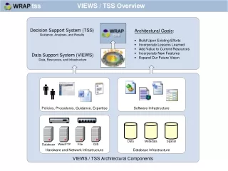
TSS system requirements Conceptual TSS architecture
Conceptual TSS architecture- basic interfaces • ESS-0037596, TSS concept • Critical process values are monitored and evaluated continuously, from the target station systems • Actuation at the Ion source and the RFQ in the Accelerator • Control (manual) and monitoring of beam direction to bypass TSS RSFs • Information of TSS status to operator in the Main control room • Benefit ICS infrastructure • Fail-safe concept • Loss of power or communication will lead to actuation Securing beam to dump , Main control room
Conceptual TSS architecture- RFPD , IEC 61226 -> IEC 61513 IEC 61226 -> IEC 62340 “NPP coping with CCF” • 5.2: For I&C systems that perform category A functions the appropriate application of redundancy combined with voting mechanisms has been proven to meet the single failure criterion. This design ensures that the likelihood of a failure of such I&C systems is very low. • 7.1: I&C systems perform their safety functions independently if a postulated failure of one of these I&C systems does not prevent the other systems from performing their functions as intended • He_T and He_P not diverse functions for all identified events for TSS • If failure of Relay train -> PLC train cannot solve He_T function • Share sensors between the trains • Galvanic isolation at sensor connection • If failure of Relay train -> PLC train not affected, not damaged and not prevented from performing its function -> PLC train will solve the He_T function He_TA He_TB He_TC He_PA He_PB He_PC Electrical isolation Relay train PLC train Ion source RFQ Stop beam
TSS system requirements Comments from pre-CDR
Comments from pre-CDR- relevant for this CDR1 and requirements • #7 “The vacuum trip point for the TSS needs to be established”. • Established according to Per’s presentation • #22“Trip thresholds need to be agreed for both the TSS and the MPS. The headroom on some of the systems seem to be marginal? The TSS team has to investigate this in more detail”. • Thresholds established with TSS, but still to be verified and potentially adjusted. • MPS thresholds not yet defined, not within TSS scope, but within Target division scope
TSS system requirements Thank you!