Download
1 / 14
791 likes | 2.79k Views
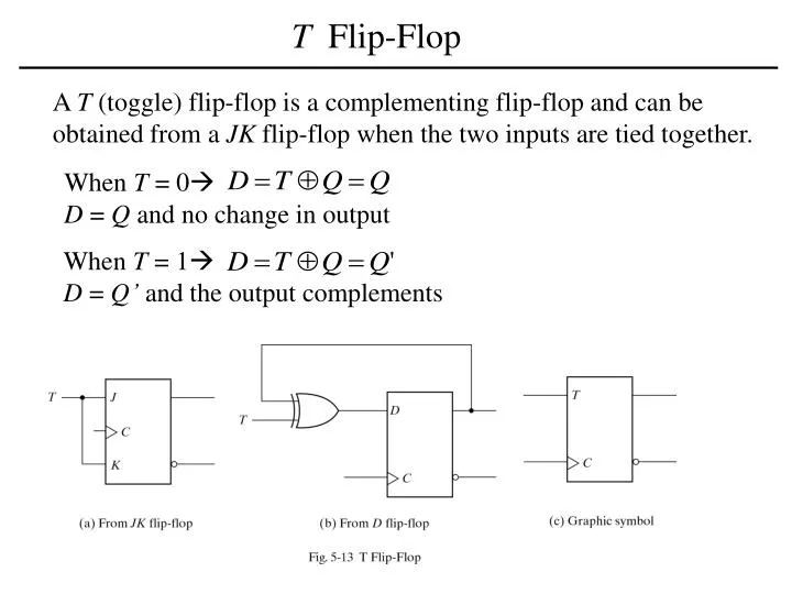
T Flip-Flop. A T (toggle) flip-flop is a complementing flip-flop and can be obtained from a JK flip-flop when the two inputs are tied together. When T = 0 D = Q and no change in output. When T = 1 D = Q’ and the output complements. Characteristic Tables and Equations.

E N D
T Flip-Flop A T (toggle) flip-flop is a complementing flip-flop and can be obtained from a JK flip-flop when the two inputs are tied together. When T = 0 D = Q and no change in output When T = 1 D = Q’ and the output complements
Characteristic Tables and Equations Q(t) = present state Q(t+1) = next state after one clock period J KQ(t+1) 0 0 Q(t) No change 0 1 0 Reset 1 0 1 Set 1 1 Q’(t) Complement TQ(t+1) 0 Q(t) No change 1 Q’(t) Complement DQ(t+1) 0 0 Reset 1 1 Set
Analysis of Clocked Sequential Circuits The behavior of a clocked sequential circuit is determined from the inputs, outputs, and the state of its flip-flops. • State Equation • A state equation (transition equation) specifies the next state as a • function of the present state and inputs. • State Table • A state table (transition table) consists of: present state, input • next state and output. • State Diagram • The information in a state table can be represented graphically in • a state diagram. The state is represented by a circle and the transitions • between states are indicated by directed lines connecting the circles.
Analysis of Clocked Sequential Circuits Analysis Procedure • Determine the flip-Flop input equations in terms of the present • state and input variables. • Substitute the input equations into the flip-flop characteristic • equation to obtain the state equations. • 3. Use the corresponding state equations to determine the next state • values in the state table.
Example of a Sequential Circuit State Equations (t+1) next state of the flip-flop one clock edge later. Flip-flop input equations (excitation equations) note mistake in Fig. 5-15 p. 181
Example of a Sequential Circuit (continued) Present Next StateInputStateOutput A B x A B y 0 0 0 0 0 0 0 0 1 0 1 0 0 1 0 0 0 1 0 1 1 1 1 0 1 0 0 0 0 1 1 0 1 1 0 0 1 1 0 0 0 1 1 1 1 1 0 1
Example of a Sequential Circuit (continued) PresentNext StateInputStateOutput A B x A B y 0 0 0 0 0 0 0 0 1 0 1 0 a 0 1 0 0 0 1 0 1 1 1 1 0 b 1 0 0 0 0 1 1 0 1 1 0 0 c 1 1 0 0 0 1 1 1 1 1 0 1 c a b a: When the sequential circuit is in present state 00 and the input is 1, the output is 0. After the next clock cycle, the circuit goes to the next state 01. b: When the sequential circuit is in present state 01 and the input is 1, the output is 0. After the next clock cycle, the circuit goes to the next state 11. c: No change in state.
Example of Sequential Circuit with JK Flip-Flops 1. Flip-Flop input equations:
Example of Sequential Circuit with JK FF (continued) 2. Substitute the input equations into the flip-flop characteristic equation to obtain the state equations. JK Flip-Flop characteristic equation Flip-Flop input equations Sequential Circuit state equations 3. Use the corresponding state equations to determine the next state values in the state table.
Example of Sequential Circuit with JK FF (continued) Present Next Flip-Flop State Input State Inputs A B x A B 0 0 0 0 1 0 0 1 0 0 0 1 0 0 0 0 0 1 0 1 0 1 1 1 1 1 0 0 1 1 1 0 1 0 0 1 1 0 0 1 1 0 0 1 1 1 0 1 1 0 0 0 0 0 1 1 0 0 0 1 1 1 1 1 1 1 1 1 1 0 0 0
Example of Sequential Circuit with T Flip-Flops 1. Flip-Flop input equations:
Example: T Flip-Flops circuit (continued) 2. Substitute the input equations into the flip-flop characteristic equation to obtain the state equations. T Flip-Flop characteristic equation Flip-Flop input equations Sequential Circuit state equations
Example: T Flip-Flops circuit (continued) Present Next StateInputStateOutput A B x A B y 0 0 0 0 0 0 0 0 1 0 1 0 0 1 0 0 1 0 0 1 1 1 0 0 1 0 0 1 0 0 1 0 1 1 1 0 1 1 0 1 1 1 1 1 1 0 0 1