Download
1 / 31
310 likes | 421 Views
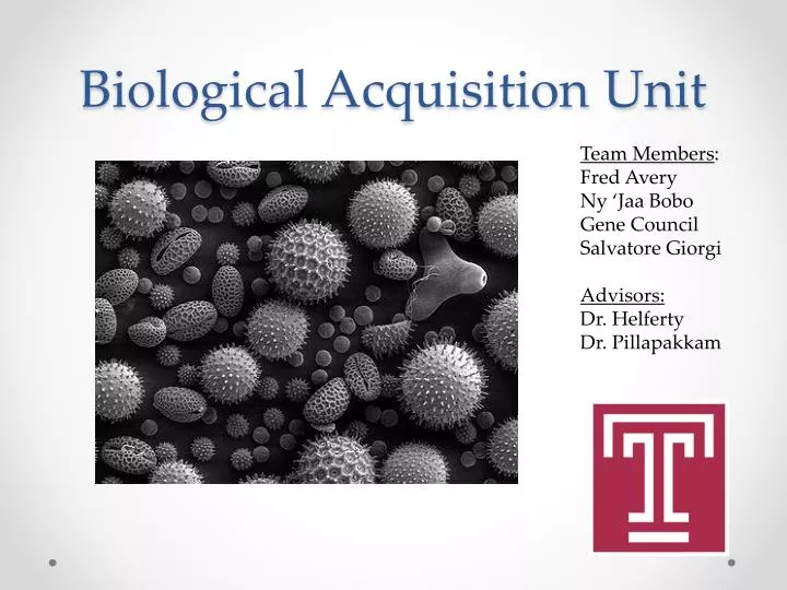
Biological Acquisition Unit. Team Members : Fred Avery Ny ‘ Jaa Bobo Gene Council Salvatore Giorgi Advisors: Dr. Helferty Dr. Pillapakkam. Outline of Presentation . Mission Overview O bjective Theory Background / Previous R esearch Biological Analysis Success Criteria Design

E N D
Biological Acquisition Unit Team Members: Fred Avery Ny ‘JaaBobo Gene Council Salvatore Giorgi Advisors: Dr. Helferty Dr. Pillapakkam
Outline of Presentation • Mission Overview • Objective • Theory • Background / Previous Research • Biological Analysis • Success Criteria • Design • Design Process • Electrical System • Physical Model • Software Flow Chart • Power System • Components • Filter System • Optical System • Design Compliance • Testing • Biological Analysis • Shared Can Logistics • Management • Schedule • Team Members • Advisors • Part List / Budget Outline • Conclusion
Objective • Measure the earth’s magnetic field as a function of altitude. • Measure flight dynamics of the rocket. • Take biological samples in stratosphere and lower mesosphere. • Mini-spectrometer will measure the absorption spectrum of the atmosphere as a function of altitude
Theory • An inertial measurement unit (IMU) is an electrical device consisting of accelerometers and gyroscopes that are used to measure the rocket’s flight dynamics (roll, pitch, and yaw). • The magnetometer will measure the strength and direction of the earth’s magnetic field. • The filtration system will collect organic and inorganic material suspended in the atmosphere. • Spectrometer measures properties of light over a specific electromagnetic spectrum, specifically UV, VIS, and NIR.
Background • Biological aerosol defined as airborne solid particles (dead or alive) that are or were derived from living organisms, including microorganisms and fragments of living things. • Include: bacteria, fungi, viruses, unicellular organisms • In 2006, the European Science Foundation funded an exploratory workshop on “Microbiological Meteorology” at the French National Agronomic Research Institute (INRA) in Avignon. • Potential roles of micro-organisms • Act as cloud condensation nuclei and to participate in radiative forcing. • Many airborne micro-organisms likely metabolize chemical components of aerosols thereby modifying atmospheric chemistry.
Previous Research • In 2008, a study identified bacterial species Bacillus subtilis, Bacillus endophyticus, and the fungal genus Penicillium. • In 2005, a study showed about 25% of the particles suspended in air in the size range of 0.2 to 5 μm are primary biological aerosol particles.
Success Criteria • Acquire Stratospheric specimen • Collect a statistically significant sample to compare to previous studies. • Amount of samples • Type of microbes • Spectrometer • Accurately measure and record atmospheric spectra • Determine environment bio samples survive in • IMU (Inertial Measurement Unit) • Accurately and reliably record data such as: • Velocity • Flight Dynamics • Gravitational Force • Magnetometer • Study magnetic field in upper atmosphere. • Compare experimental magnetic field to actual values .
Software Flow Chart Initialize System Start timer for opening / closing valve Check connections Sample Sensors (I2C, SPI, and analog pins) First Timer Finished Open Valve Sample Sensors (I2C, SPI, and analog pins) Second Timer Finished Close Valve Sample Sensors (I2C, SPI, and analog pins) Write sensor data
Power • Basic System Requirements • Microprocessor – 90 mA @ 3.3 V • Magnetometer – 0.9 mA @ 3.3 V • Gyroscope – 3.5 mA @ 5 V • XY-axis accelerometer – 15 mA @ 6 V • Z axis accelerometer – 2.5 mA @ 6 V • Spectrometer – 0.6 A @ 5 V • Sources • Voltage regulators will be used to maintain the proper amount of power for each sensor • Series of 9 V batteries will power system
Components • Magnetometer • Power: 2.5 to 3.3 V • Field Range: +/- 4 Gauss • Current: 0.9 mA • Bandwidth: 10 kHz • Weight: 50 mg • I2C interface • Gyroscope • Power: 5 V • Range: +/- 20,000 °/sec • Current: 3.5 mA • Bandwidth: 2 kHz • Weight: 0.5 g
Components • XY-axis Accelerometer • Power: 3.0 to 3.6 V • Range: +/- 37 g • Current: 15 mA • Bandwidth: 400 kHz • Serial Peripheral Interface (SPI) • Z-axis Accelerometer • Power: 3.3 to 5 V • Range: +/- 70 g • Current: 2.5 mA • Bandwidth: 22 kHz
Components Flash Memory: 512K RAM Memory: 128K Operating Voltage: 3.3V Operating Frequency: 80 MHz Typical Operating Current: 90 mA I/O Pins: 83 Analog Inputs: 16 Analog Input Voltage Range: 0V to 3.3V DC Current Per Pin: +/- 18 mA USB 2.0 Full Speed OTG controller I2C and SPI interfaces Microprocessor
Filter System Testing • All parts must be autoclave-able • Two filter systems will be constructed • One will be included one rocket • Other kept on ground • Results compared Design • Connects to two ports: Static and Dynamic • Dynamic port draws in samples • Air flow exits through the static port • Contains four filters in series • Filters are decreasing in size from 5 to 0.2 μm • Filter system terminates with NPT connector at each end • Mass Flow Rate • The mass flow rate is expected to be about 5.3×10⁻⁶ kg/s • Particle sizes ranging from 0.2 to 5 µm • Exposure Time • System will open at 30 km and close at 30 km • Based on previous data we estimate the filter system will be open for 5 min
Filter System Rough sketch of mechanical valve system Proposed placement of filter system on plate
Optical System Spectrometer Trade Study
Design Compliance • Predicted final mass is 10+0.2 lbs • Total weight of sensors is less than 3 lbs • Projected filtration system weight is less than 2 lbs • More weight needed • Payload Activation • G-switch • Center of Mass • Preliminary Solid Works projection shows this constraint can be met
Testing • Mechanical • Air Foil • Test to see if filtration system can withstand drag force • Low pressure • Contacted Physics Department at Temple and Drexel • Test to see if filtration system functions at low pressures • Spectrometer • Ability to measure spectrum while in motion • Biological • Autoclave • Test to see if filtration system can be properly sterilized • Test to see if filtration tube can be completely sealed • Electrical • Sensors • Test accuracy • Functioning Properly • Data • Test processor is properly handling incoming data • SD Card / Reader properly storing
Biological Analysis • DAPI • DAPI (6-diamidino-2-phenylindole) is a stain used in fluorescence microscopy. DAPI passes through cell membranes therefore it can be used to stain both live and fixed cells. • BRDU • Bromodeoxyuridine (5-bromo-2-deoxyuridine, BrdU) is a synthetic nucleoside that is used for detecting actively dividing cells. • Genetic Sequencing • Determines the number of nucleotides in sample’s DNA: adenine, guanine, cytosine, and thymine • Scanning Electron Microscope • Scans the sample and re-generates image to be analyzed, i.e. structural analysis of microbes
Shared Can Logistics • Sharing canister with Drexel University • Communication has been opened up between the teams • Both teams expect to use half the canister space and weight • Drexel’s proposed experiments will not effect ours • Close proximity will allow us to integrate entire canister prior to flight • Resources from both Universities will be used for testing
Team Members Fred Avery (ME) • Filtration System • Center of gravity testing • Mass Flow Rates • Ny ‘JaaBobo (EE) • Hardware • Magnetometer • IMU • Power • Gene Council (EE) • Hardware • Magnetometer • IMU • Chip programming • Salvatore Giorgi (ECE) • Team Leader • Spectrometer • Microprocessor • Data Acquisition • Filtration System
Advisors Electrical Dr. John Helferty Department of Electrical and Computer Engineering Mechanical Dr. ShriramPillapakkam Department of Mechanical Engineering Biological Dr. Erik Cordes Department of Biology
Conclusion • Concerns • Opening and closing filtration system • Properly sterilizing and maintaining sterilization of the filtration system • Properly analyzing spectrum during flight • Possible addition of second microprocessor • Recently Finished • Ordered microprocessor, accelerometers, gyroscope, magnetometer, and filter canister • Wrote libraries for SPI and I2C interfaces • Future Plans • Finalize Spectrometer / Optical port design • Purchase Spectrometer • Machine plates • Continue programming processor • Build and test filtration system