Download
1 / 75
750 likes | 926 Views
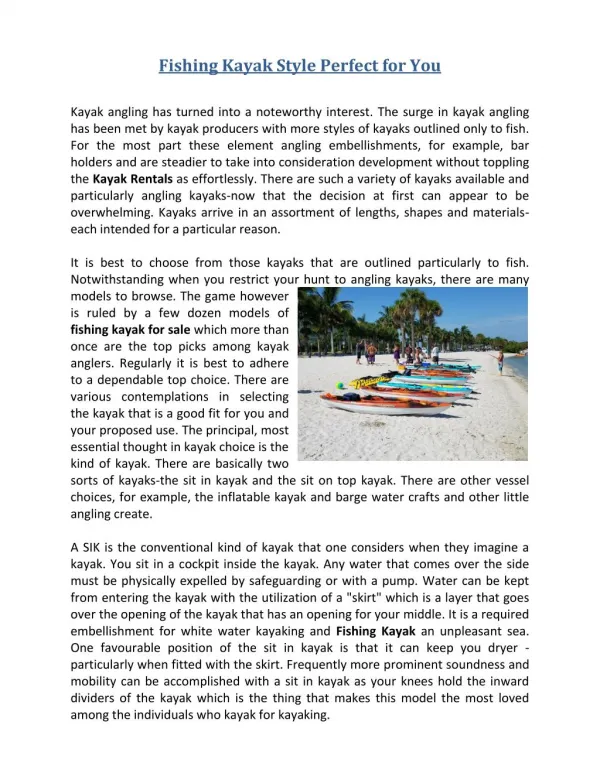
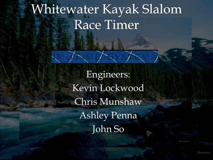
Whitewater Kayak Slalom Race Timer. Engineers: Kevin Lockwood Chris Munshaw Ashley Penna John So. Project Funded By:. Mike Neckar Founder, Necky Kayaks www.necky.com. Background on Whitewater Kayaking. Whitewater kayak slalom racing began shortly before World War II

E N D
Whitewater Kayak Slalom Race Timer Engineers: Kevin Lockwood Chris Munshaw Ashley Penna John So
Project Funded By: Mike NeckarFounder, Necky Kayakswww.necky.com
Background on Whitewater Kayaking • Whitewater kayak slalom racing began shortly before World War II • This Olympic sport involves racers paddling down a natural or man-made rive • Kayakers must maneuver through hanging pairs of gates. • Judges at shoreline determine correct maneuvering through gates.
Background on Whitewater Kayaking C1 (Canoe) on a man-made course
Background on Whitewater Kayaking K1 (Kayak) on a natural river course
Kayak Rules • The racer must proceed through green gates in the down-river direction • Red gates in the up-river direction • 2sec penalty for touch gates but going through • 50sec penalty for touch and not gone through
Present Situation • Judge watching at each gate to make sure the kayaker goes though • Judge determining if each gate has been touched • Stop-watches used in training for timing • Obvious problems: Human error, biases, judges not omniscient
OurSolution • Create a automated system which tracks a kayaker’s progress through a race course and determines if gates are touched. • Focus on creating a reliable and low cost product. Offset the cost of using humans to judge gates. • Secondary goal is timing accuracy.
Marketing • Mr. Neckar- use for training by olympic athletes- introduced in races such as national team trials (Vedder River, Chilliwack) • Scott Shipley, US national team member- promotion in the United States
Timeline • Overall, we are behind the proposed schedule by about two weeks. Our Proposed Timeline
Delays are caused by… • Waiting for sensors, microcontrollers, and RF modules to arrive. • Testing other design options. • Errors and bugs • Underestimated Integration Time • Earlier than expected deadline
Timeline The Actual Timeline
How to detect a Kayaker? • Ultrasonic beam across the gates • RF tag triangulation • IR beam across the gates
Ultrasonic Beam Advantages • not affected by environment • low noise • low power consumption Disadvantages • wide beam • difficult to integrate multiple ultrasonic sensors due to coupled interference
RF Tag Advantages • Very hard to cheat the technology • Low power Disadvantages • Difficult technology to use • Requires a high computational load to calculate location • Can be expensive
Optical Beam (Our Solution) Advantages • Narrow beam • Easy to implement • Unaffected by environment • Lower costs Disadvantages • Consumes higher power the ultrasonic • Sensitive to alignment
IR LED vs. Laser • Laser (Visible Spectrum) 650nm- coupled with a photodetector + amplifier- very high signal strength at large distances (5m +)- very narrow viewing angle- low power consumption (~20mA)- class III and above can cause retinal damage
IR LED vs. Laser • IR LED 950nm- coupled with an NPN phototransistor - very low signal strength at distances over 2m (required amplification)- wide viewing angle (35°) minimizing problem of gate flexibility- high power consumption (~100mA)- cannot cause retinal damage
IR LED: Improving Signal Quality • Ambient light shielding- used a non-reflective black paint to coat a drinking straw (this also formed a water-tight seal over the phototransistor) • Modulation- modulated the IR emitter with a 2kHz square wave- demodulating at the receiving side would filter out noise cause by reflections of sunlight off water, etc
IR LED: Improving Signal Quality • Ambient light shielding- used a non-reflective black paint to coat a drinking straw (this also formed a water-tight seal over the phototransistor) • Modulation- modulated the IR emitter with a 2kHz square wave- demodulating at the receiving side would filter out noise cause by reflections of sunlight off water, etc
IR LED: Overall System • Amplification -> Filtering -> Thresholding- Amplification boosts the output signal strength- Filtering creates a steady signal representing the amount of IR light detected- Thresholding creates a digital signal representing whether or not the line of sight is considered “broken”
IR LED: Modulation • Decreased average current consumption from 180mA overall to 110mA overall. • Waveform created using an astable 555 timer Simulation on breadboard
IR LED: Demodulation • Filtered using an LRC circuit, tuned to 2kHz
Accelerometer • Used to detect any contact with the gate • 3 axis, ±5g output range • Mounted 1 accelerometer per gate, in the lower region of the gate (added sensitivity)
Accelerometer: Signal Conditioning • Low Pass Filter: allows us to “dull” the signal and remove unwanted noise • Comparator: gives a digital signal representing whether or not the acceleration of the gate is beyond an acceptable level-> this allows us to have the system ignore low acceleration conditions such as gates swaying in the wind
Accelerometer Performance Tests • Comparator Threshold = 1.665V(red line in graph)
Future Improvements on Signal Conditioning • Have circuits printed on PCB • Use only variable resistors reference voltages in comparators • Improve demodulation circuit, possibly using an active filter
Final Sensor Signals • Two digital signals representing the clearance of a gate, and contact with a gate (both fully adjustable) • However, current consumption is becoming high (approx. 180mA) • This leads us to attempt ‘Presence Detection’
Presence Detection • Used to detect the presence of an approaching kayaker. • Used to trigger the turn on high power consuming subsystem. • Used Ultrasonic sensors • Accuracy • Immunity • Ease
Presence Detection • The sensors have an analog output proportional to the distance of an object. • Used thresholding to detect object presence • Used timing circuit to filter noise.
Presense Detection Future Upgrades • Currently we do not have a way to detect which direction the kayaker came from. • Gates are direction dependant according to whitewater kayak Rules. • We will switch to IR presence detection, due to better immunity to environment. • Will use one facing each direction in gate to determine direction of approach.
Data Communication Requirements • Reliable • Long Range • Low Power • Fast Transmission
Data Communication Solution • ZigBee Xbee Module from Maxstream • 30m range (upgrade 1mile) • Current Consumption during Transmission 45mA • UART Communication Format easy to integrate with our Micro Controller
Data Communication FutureUpdates • We can upgrade to Xbee Pro modules for an increased range. • Requires more power. • Allow software to communication back to gates. • Remote reconfiguration • Remote turn on/off
MicroController Firmware • Requirements • Very little memory needed – Simple program • USART Register for RF Modules • A/D Conversion capabilities • At least 3 inputs (IR Sensors, Ultrasonic, Accelerometer)
MicroController Firmware • Main Jobs • Get a development environment running • Integration with ultrasonic to turn on power board • Integration with IR sensors • Integration with RF modules
MicroController Firmware • Multiple Development Environments • 1) PICDEM • 1st to work
MicroController Firmware • Good Features • Easy viewing of ports • Attached LEDs to eliminate the need to probe • Multiple ways to power • MPLab compatibility • Problematic Features • Had to replace 40-pin socket • Initial running of programs • Quantity
MicroController Firmware • Multiple Development Environments • 2) OUMEX • 2nd to work
MicroController Firmware • Good Features • One LED to map outputs of interest to • Programming capabilities using MPLab • Less reliance on development board • Problematic Features • Building a cable from MPLab to ICSP • Initial running of programs • Quantity – shipping time
MicroController Firmware • Multiple Development Environments • 3) Prototype • Last and finally!!!
MicroController Firmware • Good Features • Cheap • Space saving • Easy connection to other circuits • Problematic Features • Must move to another development board to program • Determining which components were necessary
MicroController Firmware • IR Flag gets set in an interrupt • Accelerometer Flag gets set in an interrupt
MicroController Firmware • Ultrasonic Powering Sensor Circuit • Creates an interrupt which sets a flag • Main program deals with this • Output will be high when ultrasonic is high • IR sensors Circuit • Creates an interrupt which sets a flag • In main program, transmission showing the gate number and IR occurs
MicroController Firmware • Future Improvements • Automatic Gate Addressing • Sleep pins on the RF module • Polling gates for possible battery voltage
The Power • IR sensors consume around 150mA. • Portable/Inexpensive power source in a 9v battery • Provide clean power at 3v and 5v for all subsystems. • Supply should last for 8hrs of use
Power Solution • Isolated control directly from Micro Controller. • Micro Controller uses the low power Ultra Sonic sensors to trigger IR sensor circuit. • Circuit Board contains controlled outputs at 3v and 5v for high power, and continuous outputs of 3v and 5v.
Power Solution • We want our portable power supplies to last 8 hours of continuous usage • System Power Consumption Before Power Control • Total Power Required = 1.21Ahr • System Power Consumption After Power Control • Total Power Required = 0.511Ahr