Download
1 / 48
490 likes | 506 Views
Photogalvanic cells: Renewable and future energy devices for solar power and storage By Dr. Pooran Koli Assistant Professor Solar Power & Storage Lab Department of Chemistry, Jai Narain Vyas University

E N D
Photogalvanic cells: Renewable and future energy devices for solar power and storage By Dr. Pooran Koli Assistant Professor Solar Power & Storage Lab Department of Chemistry, Jai Narain Vyas University Jodhpur (Rajasthan) – 342033 INDIA
Approach of my talk * Introduction *Survey of solar power techniques *Photogalvanic cells- my research field *What is my contribution to the field of photogalvanic cells? *How photogalvanic cells compares with other similar cells? *How photogalvanic cells could be future energy source? *What to be done in the field of photogalvanic cells?
1. INTRODUCTION Some supreme truths - everyone/everything has to die, - sometimes things can happen without money, - but nothing can happen without the time & energy. Therefore, the energy is essential and unavoidable for life. Therefore, the production and use of energy is vital to the social, economic and scientific development of all the countries. 3
Presently at world level - about 70 % energy (power) is supplied by non- renewable sources, and about 30 % power is supplied by renewable sources(Source: IRENA database). Total installed power worldwide 2013 is ~5667 GW, ~ solar 173 GW (~3 % of total); Germany(100.9) >Italy (23.1) > Japan > USA > China >Spain At India level -71.4 % energy (power) is supplied by non- renewable sources, and 28.6 % power is supplied by renewable sources(Source: Report : Central electricity authority, Govt. of India). Solar power ~ 1 %. - India on pace with global trend regarding renewable energy. At my home state Rajasthan level - ~ 66 % energy (power) is supplied by non- renewable sources, and ~ 34 % power is supplied by renewable sources(Source: Report : Central electricity authority, Govt. of India). Solar power ~ 1 %. Rajasthan a bit ahead of global trend regarding renewable energy. Attracted to California because sun intensity similarity between Rajasthan (5-7 KWH day-1 m-2; 2nd highest in world) on one hand & California, Nevada, (7-9 KWH day-1 m-2; highest in world) on other hand. 4
At India level scenario of total power 2.54 lakh Mega Watt was the established power generation capacity in India as on 30 Sept,2014 (Report : Central electricity authority, Govt. of India). Out of this 2.54 lakh MW power - - 69.5 % is from fossil fuels ( 60.1 % coal, 85.9 % gas, 0.47 % diesel) - 16.1 % is from hydro power - 1.8 % is from nuclear power - 12.5 % is from renewable sources (solar power ~ 1 % , small hydro projects, bio-mass, wind power, etc.). 2632 MW solar (Guj 1000, Raj 700). 5
At Rajasthan level 9500 Mega Watt was the established power generation capacity in Rajasthan as on 31 Dec,2011 (Report : Central electricity authority, Govt. of India). Out of this 9500 MW power - - 60.2 % is from fossil fuels ( 53.2 % coal, 7.0 % gas) - 15.63 % is from hydro power - 6.03 % is from nuclear power - 18.13 % is from renewable sources (solar power, wind power, etc.).
Levels of needs of energy - At body level- supplied by food and drink At household & industrial level- this is supplied from non-renewable & renewable sources 7
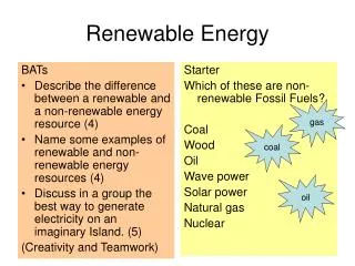
Non-renewable sources (e.g. fossil fuels- coal, petroleum, natural gas) are those energy sources which cannot be renewed after use. Beauty of Non-renewable sources– -Highly developed, highly reliable, high energy density, independent of seasonal & climatic variations, deep penetration in life, modern life owes to them, etc. Limitations of Non-renewable sources– polluting, costly, limited in stock, less abundant, geographically unevenly distributed and fastly depleting, so they cannot be safe and lasting source of energy. 8
* Renewable sources ( e.g. solar energy, tidal energy, geothermal energy ,wind energy, hydel energy, bio-energy, etc.) are those energy sources which can be renewed after use. Thus, their use is safe , clean and lasting . Limitations of Renewable sources – Less developed (except hydro), less energy density, dependent of seasonal & climatic variations, less penetration in life , etc. Beauty of Renewable sources – - their use is safe, clean and lasting . 9
Among the all renewable energy sources, the solar energy has special significance for some reasons – - it is mother of all energy resources (except nuclear energy). - It is a renewable, cheap and clean energy source. • It is most abundant source of energy, yet least harvested. - It is not certain whether life exists or not on planets other than earth but it is certain that once we master in solar energy techniques, they can be source of power on all planets. - the solar energy only can be source for power generation as long as life is on the Earth. The life can sustain on Earth only as long as the life of sun, because Earth is inhabitable due to sun radiations. In the absence of sun, the Earth will be a cold planet unable to sustain life.
Present status of solar energy at world and India level- World level- About 3 % (173 GW solar) of total power (5667 GW) coming from solar year 2013- India level – 1 % (2631 MW solar) of total power 2.54 lakh MW - JLN National Solar Plan has envisaged at least 20,000 MW of solar power generation by 2020 and up to 200,000 MW by 2050.JLN National Solar Plan is 3-phase approach (1)first phase (2010-13),1000-2000 MW, (2) Phase 2 (2013–17) ,4000-10000 MW, (3) Phase 3 (2017–22) , 20000 MW In theory, the entire present energy consumption of the world could be met by an area smaller than 1% of the world’s deserts if they were covered with solar thermal electric plants. 11
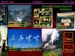
2. Solar power techniques- A survey • The solar energy can be directly converted into electricity. This electricity is called solar power. Some of the techniques for solar power generation are : 2.1. SOLAR CONCENTRATING POWER 2.2. SOLAR PHOTOVOLTAIC (SPV) TECHNOLOGY 2.3. DYE- SENSITIZED SOLAR CELL TECHNOLOGY 2.4. PHOTOGALVANIC CELLS,etc.
2.1 SOLAR CONCENTRATING POWER * This is based on concentrating solar thermal systems which uses lenses or mirrors and tracking systems to focus a large area of sunlight into a small beam. * This concentrated and small solar beam is focused on working fluids (like oil, water, hydrogen, helium, air, etc.). * The working fluid flows through the receiver and is heated up to 500 C (even up to 1500 C) before transferring its heat to a distillation or power generation system. * Thus solar energy can be converted into heat energy in turn into mechanical energy then into electrical energy.
2.2 SOLAR PHOTOVOLTAIC (SPV) TECHNOLOGY * Electricity can be produced directly from sunlight with the help of SPV technology. * SPV technology is based on the photovoltaic effect, which refers to transition of electrons from a lower to a higher energy state having absorbed photons of the right energy. * The photovoltaic effect is like photoelectric effect with a little difference. * While in the photoelectric effect, electrons are ejected from the solid, liquid and gaseous elements when light strikes on the surface of these elements, in the photovoltaic phenomenon the electrons make a transition from a lower to a higher energy state having absorbed photons of the right energy.
The SPV systems consists of two materials in contact with each other. Among them, one is wafer of electron emitting non-metal and other is electron collecting material which pass on electrons in form of electron stream (i.e. current) to circuit. The electron emitting wafer replenishes those electrons which goes out to circuit. • This technology involves semiconductors as light absorber, and electronic species (electrons and positively charged holes) as mobile charges moving in device due to mainly drift ( under the influence of electric field) and some diffusion (under the influence of concentration difference).
2.3 DYE- SENSITIZED SOLAR CELL TECHNOLOGY • These cells are made up of a porous film of tiny (nanometer sized) white pigment particles made out of titanium dioxide. • The titanium dioxide particles are covered with a layer of dye, which is in contact with an electrolyte solution. • When solar radiation hits the dye, it injects a negative charge in the pigment nanoparticle and a positive charge into the electrolyte resulting in the conversion of sunlight into electrical energy.
2.4 PHOTOGALVANIC CELLS - Photogalvanic cells are galvanic cells which have property of solar energy conversion and storage. • - This is the very simple technology on which I am working.
2.3. Experimental and calculation method - Study of variation of various parameters like conc., diffusion length, Pt size, Temp.,etc. We fill sollution of dye, reductant,NaOH, & surfactant(if used) in H-shaped tube containing SCE in one arm and Pt in oppoosite arm. 18
* The experimental set up consists of – • - H-cell (photogalvanic cell), • - light source ( different wattage bulbs), • -digital pH meter- Systronics Model:335 (for measuring potential in millivolt-mV), • microammeter-OSAW (for measuring current in microampere-µA), • - a carbon pot log 470 K device (for changing the resistance of circuit), • water filter (for filtering infrared radiations) and • a circuit key (for closing and opening circuit). 19
* The photogalvanic cell is made of glass tube of H-shape whose wall is externally blackened, but a window is left in one arm. • The arm with window acts as illuminated chamber and other arm without window acts as dark chamber . • This glass tube of H-shape is filled with known amount of the solutions of photosensitizer, reductant and Sodium hydroxide. • The total volume of the solution is always kept 25.0 ml making up by doubly distilled water. 20
* A platinum electrode (as negative terminal) is dipped in illuminated chamber against window and a Saturated Calomel Electrode- SCE( as positive terminal) is immersed in dark chamber. • The terminals of the electrodes are connected to a digital pH meter. • * Initially, the circuit is kept open and cell is placed in dark till it attains a stable potential (dark potential - Vdark). • Then, the Pt electrode is exposed to light radiations emitted from tungsten bulb. • On illumination, the photopotential (V) and photocurrent (i) are generated by the system. • The cell stand charged when maximum potential is obtained. 21
* A water filter is put between cell and lamp to cut off infra-red radiation with the aim of curbing heating effect of cell, which otherwise may adversely affect the cell leading to lower performance. • * After charging of the cell, the circuit is closed and the cell parameters like maximum potential (Vmax), open-circuit potential (Voc), maximum current(imax) and equilibrium current(ieq) or short-circuit current(isc) are measured. 22
* The study of i-V characteristics of the cell done by observing potential at different direct currents by varying resistance(calculated by Ohm law) of the circuit. • i-V characteristics shows the highest power at which cell can be used. • * The cell is operated at highest power (i.e.,power at power point - ppp) at corresponding external load, current( i.e., current at power point - ipp) and potential( i.e., potential at power point-Vpp) for study of its performance by observing change in current and potential with time. • * The cell performance is studied in terms of half change time (t0.5), conversion efficiency (CE) and fill factor (FF) in dark. 23
* The time taken for fall in the power of the cell to its half value of power at power point is called t0.5 (which is measure of storage capacity of the cell). • * The average rate of change of current over t0.5 period (∆i/∆t) is • calculated from (ipp - it0.5)/ t0.5 , • where it0.5 is current at t0.5 .The potential corresponding to it0.5 is Vt0.5. • * The charging time (t) is calculated as, • charging time = (time at which Vmax is obtained) – (time at which illumination is started). • * Photopotential (∆V) is equal to Vmax – Vdark . 24
* The CE and FF of the cell are calculated from equations (1) and (2),respectively. …(1) Where, Vpp is potential at power point and ipp is current at power point . …. (2) Where,Vppis potential at power point,ippis current at power point, Vocis open – circuit potential, andiscis short-circuit current. * The initial pH of the mixture of solutions has been calculated by the formula, pH = 14 - pOH * Lamps of different wattage have been used to vary the light intensity. 25
riplet state being relatively more stable than singlet state has role in storage capacity. 2.4 Mechanism of solar power generation & storage • Both singlet and triplet excited states of dye are involved here, but triplet state being relatively more stable than singlet state has role in storage capacity. • The main electroactive species are the leuco or semi dye and the dye in the illuminated and the dark chamber, respectively. However, the reductant and its oxidized product act only as electron carriers in the path(Tamilarasan R, Natarajan P.Photovoltaic conversion by macromolecular thionine films. Nature 1981;292: 224 – 225, & Kaneko M, Yamada A. Photopotential and photocurrent induced by a tolusafranine ethylenediaminetetraacetic acid system. Journal of Physical Chemistry 1976; 81: 1213-1215). 26
Inside the cell, there is only diffusion controlled motion of ions in solution. Therefore, photogalvanic cell requires that incident light be absorbed close to the light electrode in order to enable the electron-rich species to reach the electrode by diffusion within its lifetime. It is intended to be achieved by blackening H-cell externally and keeping a small window for illumination of platinum electrode. Further, the higher diffusion retards energy wasting reverse reaction (electron transfer from Pt electrode to dye, and from dye to reductant in illuminated chamber) (Gomer R. Photogalvanic cells. Electrochim. Acta1975, 20, 13-20.)and increases isc leading to improvement in overall performance of the cell (Shiroishi H, Yuuki K, Michiko S, Takayuki H., Tomoyo N, Sumio T, Masao K. Virtual Device Simulator of Bipolar Photogalvanic Cell. Journal of Chemical Software 2002;8:47–54).. 27
2.4 PHOTOGALVANIC CELLS 2.4.1 Introduction • The photogalvanic cell technique provides a promising and unexplored method for solar power generation and storage. • Photogalvanic cells based on solution of dye photosensitizer, reductant, and NaOH are portable energy devices for decentralized solar power generation and storage. They are cheap, renewable, and relatively eco-friendly promising energy sources for the future. They have good electrical out, power storage capacity and efficiency.
* The photogalvanic cell is a photoelectrochemical device involving ions as mobile charges moving in solution through diffusion process. * In this cell, the solution is the absorber phase contacted by two electrodes with different selectivity to the redox reaction. * Alternatively, we can say that in the photogalvanic cell, a dye in solution is photoexcited (energy rich product), which in turn can lose energy electrochemically to generate electricity with inherent storage capacity, which makes them superior to photovoltaic cells.* There is no consumption of chemicals during charging and de-charging of these solar cells(Tamilarasan R, NatarajanP.Photovoltaic conversion by macromolecular thionine films. Nature 1981;292: 224 – 225).
2.4.2. Survey of photogalvanic cells*First of all, Rideal and Williams observed the photogalvanic effect during the action of light on the ferrous iodine- iodide equilibrium, which later on was systematically investigated by Rabinowitch in Fe (II)-Thionine system.* Rabinowitch suggested that the photogalvanic effect might be used to convert sunlight into electricity. * To explore this suggestion, some photogalvanic cells using the iron-thionine system as the photosensitive fluid were tested . The observed maximum power conversion efficiency was 3 × 10⁻⁴ per cent.
* The principal reason for the low efficiency was shown to • be polarization of the polished platinum electrodes and • rapid loss of the photochemical activity of the dye. • * Coating the electrodes with platinum black reduced polarization sufficiently. • In principle, it appeared possible to make further increases in efficiency by increasing electrode area and decreasing the electrolyte resistance. • * The maximum power conversion efficiency that could be • achieved from a photogalvanic cell is between 5 & 9 % .
* Photogalvanic cells have been studied • based on- • Chlorophyll-a plated Pt electrode and Chlorophyll-a • free Pt electrode separated by a salt bridge, • aqueous ferric bromide, • ruthenium complex of dye , • chromium complex in a Honda Cell, • micro-emulsions with micellar solution, etc.
In beginning,photogalvanics emphasized on coated Pt electrode with ferrous ion as reducing agent. • Later on,the researcher started using - non-coated Pt electrode with saturated calomel electrode, - dyes like methylene blue , azure-B , azure-A , fluoroscein ,toluidine blue , etc., - organic reductants like mannitol ,oxalic acid ,EDTA , etc. and - surfactants like sodium laurylsulphate ,Tween-80 , etc. Friends, I belongs to this later group of researcher. I have chosen it because fabrication of cell is very easy, simple, and cheap.
My contribution to the field of photogalvanics-1. Used following systems-- Brilliant Cresyl Blue dye - Fructose reductant system [Fuel, 90 (2011) p.3336] - Rhodamine B dye – Fructose reductant [Renewable Energy, 37 (2012) p.250]- Fast Green FCF- Fructose Photogalvanic cell [Applied Energy,118 (2014) p.231]-Naphthol Green B dye photosensitizer in Photogalvanic cells [Applied Solar Energy, 50(2014) p.67]- Sudan I dye in natural sunlight [Arabian Journal of Chemistry,ARABJC-14-015,accepted on 25 Nov.2014]- Comparative study of various synthetic dye and natural photo sensitizer present in spinach extract [RSC Advances, 4 (2014) p.46194]- shown that under similar conditions, all sensitizers single as well as mixed gives nearly same result. Therefore, people should focus on cheap and renewable sensitizers[RSC Advances, 4 (2014) p.46194].
My contribution to the field of photogalvanics-…… - By very simple means like use of small size Pt, SCE component of combination electrode, relatively more NaOH, cleaning Pt, etc. Interesting fact lack of Pt and SCE proved blessing in disguise for me. 35
Comparison with other similar cells--There are various other cells (like Photovoltaic cell- PV, Dye sensitized solar cells(DSSC), etc.) which directly converts sunlight in to electricity as do the photogalvanic cell. -- It is concluded that photogalvanic cells may be promising future devices for solar power and storage. It is also viewed that the photogalvanic cells, with additional advantage of low cost and storage capacity, can give electrical output comparable to that for commercially used power storage property lacking photovoltaic cells.-The PV cell may be taken as a yardstick for comparison and knowing the status of development of the different kinds of cell as PV is the only cell which is being used commercially world over. 36
I see photogalvanic cells as promising source for future due to following beauty of these cells-1. high electrical output2. short charging time, 3. can be charged even in very low intensity illumination even inside room lacking direct illumination4. tremendous inherent storage capacity,5. easy & simple construction,6. reversibility with cycle of charging and discharging7. solution if disposed off is easily degradable as dye chemicals are already photo decayed to some extant,8. solution can be used in cleaning9. easy to replace solution10. SCE and Pt reusable and non-consumable11. expected cost low as no extra storage device is needed, and all materials are durable and reusable. 37
What should be done now in photogalvanic cells1. use of only renewable sensitizers as all sensitizers give same result 2. design new electrodes, vessels as all sensitizers give same result3. study of assembly of cells for actual application 38
Thanks 39
*At [Sudan-I]=10.37 x 10⁻⁵ M[Fructose] = 2.37 x 10⁻³ M, [NaLS] = 1.48 x 10⁻² M, Pt electrode area = 0.4x 0.2 cm2, natural sunlight intensity=100 mWcm-2, diffusion length (DL) = 6.3 cm,pH =13.74. 40
ductant. For each system, the cell performance is found to be dependant on the concentration of the reductant, and the highest cell performance is observed at an optimum concentration of reductant. The reason for this observation may be that on the lower side of concentration range of Fructose, there will be limited number of Fructose molecules to donate electrons to dye, therefore, there is low electrical output at lower concentrations of Fructose whereas higher concentration of Fructose will not permit (i) the desired light intensity to reach the dye molecules, and (ii) will also hinder the motion of dye molecules towards electrodes and hence, there will be corresponding fall in power of cell.Reducing agent indeed acts as a regenerable electron carrier [Tamilarasan R, NatarajanP.Photovoltaic conversion by macromolecular thionine films. Nature 1981;292: 224 – 225; and Kaneko M, Yamada A. Photopotential and photocurrent induced by a tolusafranineethylenediaminetetraacetic acid system. Journal of Physical Chemistry 1976; 81: 1213-1215].
For each system, the cell performance is found to be dependant on the diffusion length, and the highest cell performance has been observed at an optimum diffusion length.Diffusion length significantly affects performance of photogalvanic cells as they are based on diffusion of ionic species. It has been observed that with an increase in diffusion length, the photocurrent showed an increase and potential showed decrease . As diffusion length increases, the current increases as conductivity of dye increases due to increase in volume of solution between electrodes. The potential decreases with diffusion length. The reason is that concentration gradient disturbs the dye (double layer) layer on Pt electrode. As diffusion length is small, concentration gradient factor is reduced and potential is increased.
* With an increase in the temperature, the photocurrent (imax) of the photogalvanic cell is found to increase with a corresponding fall in Voc. * The change in voltage is much stronger than the change in current. * It is observed that with the increase in temperature (temperature range under observation) the power output of the cell increase slowly irrespective of the fall in photopotential. With temperature rise, the double layer on Pt is disturbed due to thermal motion. * So, the potential decreases with temperature rise. * With temperature rise, the thermal motion and diffusion of ions increases leading to higher current.
* The photocurrent and photopotentialshows a increasing behaviour with the increase in light intensity. The increased light intensity increases the number of photons per unit area (incident power) striking the dye (photosensitizer) molecules around the platinum electrode and, therefore, an increase in the electrical output. * At lower light intensity, the number of photons may be few in comparison to dye molecules leading to few numbers of dye molecules for electron donation to Pt electrode .As the light intensity increases, the numbers of dye molecules for electron donation to Pt electrode increases and hence electrical parameters also increases. * At very high light intensity, the performance of cell decreases for probable reasons – (i) the dye molecules are limited in number, so large number of photons remains unutilized, (ii) there is relatively less increase in power but high increase in intensity leads to lower efficiency as intensity is in denominator of formula of conversion efficiency, and (iii) higher intensity causes higher heating effect on cell leading to relatively poor performance of the cell. A water filter is used to cut off the thermal radiations and mitigate the heating effect.
* For the observed effect of electrode area, the better cell parameters is found for small electrodes owing to relatively less hindrance to diffusion of ions.
* the variation of potential with time (during charging) is as - Fig. Variation of potential with time We see that potential rises with time and reaches to a highest value that is maximum potential as also shown in Fig.
* Variation of current with potential (i-V characteristic) and power is as - Fig. Variation of current with potential (i- V characteristic of the cell) for Rhodamine B- Fructose System. We see that there is inverse relation between current and potential. It means potential increases as the current is decreased.
* The variation of power with current is as in Fig. – Fig. Variation of power with current for Rhodamine B – Fructose System. We see that maximum power from cell is obtainable at some middle current (460 µA). 48