Download
1 / 10
100 likes | 207 Views
LGS for SAM Design Review September 2007, La Serena. LGS for SAM Optical Alignment. R.Tighe, A.Tokovinin. Laser Box on one of the serrurier trusses at bent-cass port #2 at 45Deg from IR Nasmyth. The SOAR Maximum Flexure (Top Ring w/r to Elevation Ring): (Top Ring w/r to Optical Axis):.

E N D
LGS for SAM – PDR – Optics LGS for SAM Design Review September 2007, La Serena LGS for SAM Optical Alignment R.Tighe, A.Tokovinin.
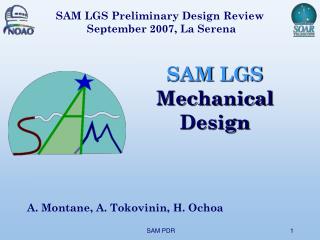
LGS for SAM – PDR – Optics Laser Box on one of the serrurier trusses at bent-cass port #2 at 45Deg from IR Nasmyth. The SOAR Maximum Flexure (Top Ring w/r to Elevation Ring): (Top Ring w/r to Optical Axis): • Displacement [Y]≈ 2mm. • Tilt [Qx] ≈ 1 Arcmin. IR Nasmyth Optical Nasmyth • Tilt [Qx] ≈ 20” (5” corr.ON). Beam Transfer Laser Launch Telescope Note: As shown in SAM SDN; SAM-AD-02-6301 (SOAR flexure measurements), the flexure seems due to elevation ring sag. Mounting the laser box on the truss should decrease the effect. So the expected flexure is less than the above values. Flexure measurements of SOAR
LGS for SAM – PDR – Optics ~1.5m UV Laser Blue Laser • Co-align UV and Blue Lasers,e.g. by center and auto-collimationfrom a distant target (~10m) or any other method, Laboratory work. ~10m Alignment Mirrors Am1&Am2 (coating450-700nm) The Laser-Box Alignment
LGS for SAM – PDR – Optics LLT m3 m4 SOAR Elevation Ring IR The LGS beam transfer Adjustments(Alignment done with the blue laser) • The m3 Adjustments: Tilts:Qx=±2º; Qy=±2º. Auto-collimation back to Laser. • The m4 Adjustments: Active Tilts:Qx=±2º; Qy=±2º. Target on LLT entrance. • The Laser Box Adjustments: Tilts:Qx=±0.5º; Qy=±0.5º. Target on m4. Beam Transfer
LGS for SAM – PDR – Optics LLTm2 Center of curvature LLTm2 focus LLTm1focus LLTm2 Step 1: The general procedure: • Center and Auto-collimate from LLTm2. • X-Y (and Z) displacement of LLTm1 until the foci of both mirrors are coincident. • Tip-Tilt LLTm1 pivoting around the common focal point, until beam is centered in LLTm1. • The active tip-tilt of m4 will keep the beam centered on LLTm2 (and LLTm1) and therefore IQ stays coma free up to ~1º of LLT pointing correction (need < 1’). LLTm1 The LLT Alignment
LGS for SAM – PDR – Optics • Step 2: In the Laboratory: The auto-collimated beam (into CCD or back to Laser) is measured with a WFS. 485mm • Step 0: The general procedure. Center and Auto-collimate from LLTm2. Re-center (or tilt) LLTm1 to make both mirrors’ foci coincident. 8mm parallel beam only Center Field The LLT Alignment
LGS for SAM – PDR – Optics • Step 3: 1rst Pointing Alignment. The Optical Axes of the LLT and SOAR telescope are made coincident by Tip-Tilting the LLT as a whole (daytime). The LLT Alignment
LGS for SAM – PDR – Optics • Step 4: 2nd Pointing Alignment and m3 Adjustment. The Optical Axes of the LLT and SOAR telescope are fine tuned with a Star image and m3 is adjusted to mount LLT onto the beam transfer optics. • The m3 final Adjustment: Two checks: 1) Laser auto-collimation (flat mirror on LLT). 2) Star image in CCD- camera at m4 or at laser box. • The Pointing Tuning: Image the star in the predefined position on the LLT alignment & pointing CCD camera. The LLT Alignment
LGS for SAM – PDR – Optics 8mm Gaussian Beam Exit Window Soleil-Babinet Compensator • Laser GB quality control: Power Check replacing beam-dump with power-meter. Also a photodiode checks the LLT outgoing beam. M² check with Beam profiler. 8x Beam Expander Beam Profiler CCD Alignment Mirrors Am1&Am2 (coating450-700nm ) Beam Dump / Power meter 355nm laser-line Dump switch-Mirror • GB centering on LLTm2: By 4 photodiodes at the edge of LLTm1. ~1.5m Intra-cavity Shutter Blue Alignment Laser (473nm) (or better400-420nm?) VIS • LGS quality control: Flux return and spot size in the LGS WFS. 355nm Tripled Nd:Yag Laser UV • LLT alignment control: Donut (or defocused star) image on LLT alignment/pointing CCD camera. The LGS beam Control
LGS for SAM – PDR – Optics Experiments and To Do List Experiments: • Test the Beam-Expander. Parallel beam and waist image formation as well as chromatic focus differences. • Test the S-B compensator and measure phase shifts. • Test the Beam profiler and Power meter. Calibrate photodiodes. To Do: • Purchase the Laser-Box and beam transfer optics. • Refine the LLT Opto-mechanical design and do the optical procurement.