Download
1 / 47
470 likes | 676 Views
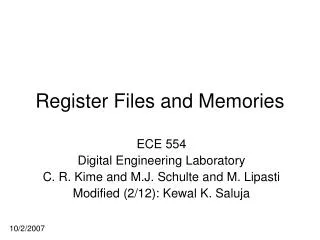
Register Files and Memories. ECE 554 Digital Engineering Laboratory C. R. Kime. 2/18/2002. Register Files and Memories. Register Files Issues and Objectives Register File Concepts Implementation of Register Files Workarounds For Xilinx FPGAs Bottom Line Memories Timing Issues

E N D
Register Files and Memories ECE 554 Digital Engineering Laboratory C. R. Kime 2/18/2002
Register Files and Memories • Register Files • Issues and Objectives • Register File Concepts • Implementation of Register Files • Workarounds For Xilinx FPGAs • Bottom Line • Memories • Timing Issues • Width Expansion ECE 554 - Digital Engineering Laboratory
Issues and Objectives • Issues • ECE 554 projects require a broad range of register file and memory configurations • ECE 554 lab boards provide very limited structures for implementing register files and memories. • Objectives: • To develop techniques for implementing a broad range of register file and memory configurations by using with available lab board structures ECE 554 - Digital Engineering Laboratory
Register File Concepts • Register file environments • Non-Pipelined • Pipelined • Register File Configurations • Address Ports • Data Ports • Control Ports • Timing • Latch • Flip-flop ECE 554 - Digital Engineering Laboratory
RAddr B CLK Rdata B WEn ALU WAddr C Wdata C Rdata A RAddr A Environment - Non-Pipelined • Input Wdata C not registeredoutside of Register File • Inputs WEN and Waddr C may or may not be registered ECE 554 - Digital Engineering Laboratory
RAddr B CLK Rdata B ... ... WEn ... ALU WAddr C Wdata C Rdata A RAddr A CLK CLK Environment - Pipelined 1 • Register File is part of pipe platform • Inputs may or may not be registered ECE 554 - Digital Engineering Laboratory
Raddr B ... Rdata B ... ... WEn ... Waddr C ... Wdata C Rdata A Raddr A CLK CLK Environment - Pipelined 2 • Register File • is between pipe platforms • is not clocked - WEN controls latches => SRAM • Inputs • may or may not be registered, but • register must be between Rdata A, Rdata B, and Wdata C ECE 554 - Digital Engineering Laboratory
Register File Ports • Address • Read • Write • Shared • Data • Input • Output • Bidirectional • Control • Write Enable, Read/Write, Enable, Read, Write, CLK ECE 554 - Digital Engineering Laboratory
Register File Configurations • Port Counts • Number of each of six types of address and data ports • Control Port Types • Selection of types of control ports from list • Port Associations • Association of address ports with data ports • Association of control ports with data ports • Data Output Data Bidirectional • Control ECE 554 - Digital Engineering Laboratory
Timing • Latch • Flip-flop • Latch Pairs • Shared Slave Latches • Shared Master Latches ECE 554 - Digital Engineering Laboratory
WEn ... Waddr Write Logic ... ... Read Logic Rdata ... Wdata ... Raddr Latch-Based • Latch/bit of file • Latch control can be Write Enable and addresses or some combination of other signals and addresses ECE 554 - Digital Engineering Laboratory
Latched-Based • Level-sensitive write • Setup time on write address relative to leading edge of Wen • Hold time on write address relative to trailing edge of Wen • Setup and hold time on write data relative to trailing edge of Wen • Cannot be part of a pipeline platform in a single clock (flip-flop based) system • Latches cannot be in closed loop without: • Additional latch on different clock in loop, or • Flip-flop in loop ECE 554 - Digital Engineering Laboratory
WEn ... Waddr Write Logic ... ... Read Logic Rdata ... Wdata CLK ... Raddr Flip-flop (Latch Pair)-Based • Flip-flop/bit of file • Flip-flop is clocked by CLK or some combination of CLK and other signal and enabled by addressing logic and combination of other signals ECE 554 - Digital Engineering Laboratory
Flip-flop (Latch Pair)-Based • Write Logic adds setup-time to that for flip-flops • Read Logic adds propagation delay to that for for flip-flops • Acts like positive pulse master-slave or negative-edge triggered flip-flop register file with above delays added ECE 554 - Digital Engineering Laboratory
Flip-flop (Shared-Slave)-Based • Latch/bit of file plus latch/bit of output • Master latches are clocked by CLK some combination of CLK and other signal and enabled by addressing logic and combination of other signals; slave latches clocks by CLK WEn ... Waddr Write Logic ... ... ... Read Logic Rdata ... Wdata CLK ... Raddr CLK ECE 554 - Digital Engineering Laboratory
Flip-flop (Shared-Master)-Based • Latch/bit of file plus latch/bit of input • Master latches are clocked by CLK some combination of CLK and other signal and enabled by addressing logic and combination of other signals; slave latches clocks by CLK WEn Waddr ... ... Write Logic ... ... Read Logic Rdata Wdata ... ... ... ... Raddr CLK CLK ECE 554 - Digital Engineering Laboratory
Implementation of Register Files • Custom VLSI SRAM • Classic SRAM • Xilinx Virtex SRAM • Specifications • Shortcomings ECE 554 - Digital Engineering Laboratory
Custom VLSI SRAM • Is the most flexible of all implementation techniques • Can be used to implement any combination of variants discussed • Latch-based straightforward; needs additional rank of latches to do flip-flop-based • Short of performance issues due to capacitance, can implement any port configuration in a singe storage element array. ECE 554 - Digital Engineering Laboratory
Classic SRAM • Has single RWaddr port, single Wdata port, and single Rdata port and is latch-based. • Due to single address port, can handle only one R or W access per clock cycle • Since latch-based, cannot serve as part of a pipe platform - hence Pipelined 2 form • Expansion to n R address/data ports • Place n SRAMs in parallel with the write accomplished by: • Applying same address to all Rwaddr, and • Wiring together all Wdata ports • Expansion to m W address/data ports • Add an m-way multiplexer to address port • Use a clock that is m times CLK and multiplex the writes over m clocks ECE 554 - Digital Engineering Laboratory
Classic SRAM (Continued) • Addresses must be switched on positive clock edge • WEn must be generated from negative clock edge and positive clock edge • Expansion to m W address/data ports and n R address/data ports • Doing both expansions above • Using (m +1)-way multiplexer, and • A clock that is (m + 1) times CLK • Virtex Distributed SelectRAM • The SRAM capability provided in CLBs • Can be used with expansion methods here in classic asynchronous SRAM mode or some synchronous modes • Getting reliable timing is tricky - may require more complex clocking! • See Old Register File writeup on website ECE 554 - Digital Engineering Laboratory
RAMB4_S# WE EN RST DO[#:0] CLK ADDR[#:0] DI[#:0] Virtex Block SRAM Specifications • Symbol - Single Port ECE 554 - Digital Engineering Laboratory
RAMB4_S#_S# WEA ENA RSTA DOA[#:0] CLKA ADDRA[#:0] DIA[#:0] WEB ENB RSTB DOB[#:0] CLKB ADDRB[#:0] DIB[#:0] Virtex Block SRAM Specifications • Symbol - Dual Port ECE 554 - Digital Engineering Laboratory
Virtex Block SRAM Specifications • Functionality • A WRITE operation of data DI to address ADDR occurs for WE = 1, EN = 1, RST = 0 and a positive edge on CLK. DI can also be read on DO after a delay. • A READ operation from address ADDR occurs for WE = 0, EN = 1, RST = 0 and a positive edge on CLK. • A RESET operation occurs on the DOA latches only for EN = 1, RSTA = 1, and a positive edge on CLK ECE 554 - Digital Engineering Laboratory
Virtex Block SRAM Specifications • Functionality • CLK, EN, WE, and RST can also be programmed to be active low • Conflicts for Dual Port SRAM • Simultaneous WRITEs to same location give invalid data • A simultaneous READ on the alternate port of a location being written gives invalid READ data • A READ on the alternate port of a location being written may not be performed until after a clock-to-clock setup window ECE 554 - Digital Engineering Laboratory
Virtex Block SRAM Specifications • Functionality - Timing • EN, WE, RST, ADDR, DI are captured on the positive edge of CLK in registers (unclear whether latches or flip-flops) • WRITEs into the SRAM latch array occur later due to internal timing logic • READs (including those associated with writes) occur later due to internal timing logic ECE 554 - Digital Engineering Laboratory
Virtex Block SRAM Shortcomings • Using Dual Port Virtex Block SRAM with custom VLSI SRAM used as the standard for comparison • On a single clock cycle: • Maximum of two independent READ or WRITE operations • Maximum of two READbacks of written value from WRITE operation on same port possible • READback of written value from WRITE on alternate port not possible ECE 554 - Digital Engineering Laboratory
Virtex Block SRAM Shortcomings • Additional implication of conditions on prior page: • Since the Virtex Block SRAM has two addresses, it should support operands for a binary operation: R[ADDRA] <= R[ADDRA] op R[ADDRB] for arbitrary ADDRA and ADDRB on each clock cycle. • But, it does not! • Since it is READ-after-WRITE, the right hand side operands are read in clock cycle i and the left hand side result is written in clock cycle i+1. One of the two addresses on the right hand side for cycle i must be the same as the write address on the left hand side for cycle i. This gives an inter-operation address dependency, an architectural disaster! • Further, the READ-after-alternate port-WRITE problem causes the transfer R[ADDRy] <= R[ADDRx] op R[ADDRx] to be impossible to execute after a write to ADDRx. ECE 554 - Digital Engineering Laboratory
Virtex Block SRAM Shortcomings • Positive edge-triggered storage of inputs to SRAM places an implicit register in from of the SRAM • Combinational READs with address changing, for example, on both the leading and trailing edge of clock, impossible • Feeding the SRAM array directly from combinational logic impossible • Latching of outputs • Combinational READs impossible ECE 554 - Digital Engineering Laboratory
Why Did Xilinx Produce Such a Design? • I can only guess - perhaps you have better ideas. • Guess 1: Excessive obsession with potential timing problems • In terms of critical timing on signals into SRAM, with the interconnect delay uncertainty in the FPGA, these concerns are realistic • Based on their past experience with customers based on Distributed SRAM use, although we made it work with some conservative clocking methods • Output latching is to make it look like true long delay FF outputs - ridiculous requirement! • Guess 2: The designers didn’t understand the range of applications well, e.g., expectations for register files ECE 554 - Digital Engineering Laboratory
Workarounds for Virtex FPGAs • Absorbing input registers • READ-after-alternate port-WRITE • READ port expansion • Inter-operation address dependency removal • WRITE port expansion • Absorbing output latches ECE 554 - Digital Engineering Laboratory
Absorbing Input Registers • Non-Pipelined - looks like PET flip-flop- based file - no absorbing needed! RAMB4_S#_S# WEA ENA RSTA CLK DOA[#:0] CLKA ADDRA[#:0] DIA[#:0] ALU WEB ENB RSTB CLK DOB[#:0] CLKB ADDRB[#:0] DIB[#:0] ECE 554 - Digital Engineering Laboratory
RAMB4_S#_S# WEA ENA RSTA DOA[#:0] CLKA ADDRA[#:0] DIA[#:0] WEB ENB RSTB DOB[#:0] CLKB ADDRB[#:0] DIB[#:0] Absorbing Input Registers • Pipelined 1 - Register file part of pipeline platform - looks like PET flip-flop-based file - no absorbing needed! CLK ... ALU ... ... Pi Pj CLK CLK CLK ECE 554 - Digital Engineering Laboratory
Absorbing Input Registers ... • Pipelined 2 - Register file as SRAM between pipeline platforms - input registers give unwanted platform - must absorb into Pi and Pj platforms • Combinational logic between Piand SRAM now placed before Pi ... Pi RAMB4_S#_S# ... WEA Pi ENA RSTA DOA[#:0] CLKA CLK Pi ADDRA[#:0] ... ... Pj Pj DIA[#:0] WEB Pi ENB ... RSTB DOB[#:0] CLK CLKB ADDRB[#:0] Pi DIB[#:0] CLK ECE 554 - Digital Engineering Laboratory
Absorbing Input Registers • Summary • Non-pipelined - No problem • Pipelined 1 - No problem • Pipelined 2 - Problem • Handle by moving pipeline platform pieces • Handle by converting to Pipeline 1 form • Affects combinational delay distribution between stages and hence may affect pipeline performance ECE 554 - Digital Engineering Laboratory
READ-after-alternate port-WRITE CLK Select P RAMB4_S#_S# 1 WEA • Add bypass logic outside of Virtex Block SRAM: ENA RSTA 0 DOA[#:0] CLK CLKA ADDRA[#:0] DIA[#:0] WEB ENB = RSTB 0 DOB[#:0] CLK CLKB ADDRB[#:0] DIB[#:0] 1 P Select CLK ECE 554 - Digital Engineering Laboratory
Read Port Expansion • Expansion to n R address/data ports • Place ceiling(n/2) SRAMs in parallel with the two writes accomplished by: • Applying same address to all ADDRA and the same address to all ADDRB, and • Wiring together all DIA ports and all DIB ports ECE 554 - Digital Engineering Laboratory
Read Port Expansion RAMB4_S#_S# WEA ENA ENA ENA1 RSTA CLK WADDRA DOA[#:0] CLKA ADDRA[#:0] • Example for n = 4 RADDRA1 DIA[#:0] ENB WEB ENB ENB1 RSTB CLK WADDRB DOB[#:0] CLKB ADDRB[#:0] RADDRB1 DIB[#:0] DIA RAMB4_S#_S# DIB WEA ENA ENA2 RSTA CLK DOA[#:0] CLKA ADDRA[#:0] RADDRA2 DIA[#:0] Select for all A mux’s is WEA and all B mux’s is WEB All other like-named signals connected together WEB ENB2 ENB RSTB CLK DOB[#:0] CLKB ADDRB[#:0] RADDRB2 DIB[#:0] ECE 554 - Digital Engineering Laboratory
Inter-operation Address Dependency • READ-after-WRITE - Can be done for one WRITE - two READs with two parallel Dual Port Block SRAMs with READ-after-alternate port-WRITE logic added to READ side of both. • Parallel WRITE on A ports • Independent parallel READs on B-ports • Each additional parallel Dual Port Block SRAM adds one more READ port • Cannot accomplish WRITE-after-READ • Cannot be done for more than one active WRITE port without using WRITE Port Expansion ECE 554 - Digital Engineering Laboratory
Write Port Expansion • Requires “super-clocking,” in which a clock having a multiple of the frequency of the fundamental operational clock is used to serialize Block SRAM operations. • Requires additional registers to locally enter into and return from serialized operations • Muxes required that are switched by the a flip-flop driven by the faster clock ECE 554 - Digital Engineering Laboratory
Write Port Expansion Pi1 Pj Pi -1 2CLK RAMB4_S#_S# • Example - Non-Pipelined - 4 WRITE Max ports WEA ENA 2CLK RSTA 2CLK DOA[#:0] CLKA 2CLK ADDRA[#:0] DIA[#:0] WEB ENB RSTB DOB[#:0] CLKB 2CLK 2CLK ADDRB[#:0] DIB[#:0] Pi2 CLK CLK ECE 554 - Digital Engineering Laboratory
Absorbing Output Latches • The output latch is a part of the attempt at a “flip-flop” appearance for the SRAM operation. • As such, there appears to be no way to explicitly work around it • Other workarounds handle its effects ECE 554 - Digital Engineering Laboratory
The Bottom Line • Overall, it appears that the best approach is to: • Use a Non-Pipelined or Pipeline 1 structure • Use the Interoperation Dependency solution to achieve multiple dependency-free READs • Use WRITE Port Expansion for multiple WRITEs • Use the READ-after-alternate port-WRITE to get READ-after-WRITE capability • Use WRITE Port Expansion with READs on early subcycles to get WRITE-after-READ capability • Be cognizant of substantial setup times and delays for the synchronous operations • Feel free to experiment with other approaches and apply ideas given to other Virtex Block SRAM uses ECE 554 - Digital Engineering Laboratory
Memories • Timing Issues • Width Expansion ECE 554 - Digital Engineering Laboratory
Timing Issues • The off-board SRAMs are asynchronous and have typical signal timing requirements • See AS7C4096 Datasheets for timing parameters • Address controlled READ is easy • WE-controlled WRITE has zero setup and hold times which look easy, but read on • Due to unpredictable FPGA timing, timing of memory signals, particularly for WRITE should be verified. • In worst case, may need to use “super clocking” to get reliable timing ECE 554 - Digital Engineering Laboratory
Width Expansion • Width expansion can be achieved by using “super clocking” with implementation similar to that for register file write expansion. • To expand a 16-bit word to a 16 n bit word requires “super clocking” at n times the fundamental rate. ECE 554 - Digital Engineering Laboratory
Width Expansion • Implementation • For address-controlled READs, straight-forward • Not recommended, although feasible, for WRITEs: • Must be trailing edges on, for example, WE, for each of the super clock cycles • This will require changes on negative as well as positive super clock edges ECE 554 - Digital Engineering Laboratory
Postscript • The workarounds do not consider: • Multiple clock edge use instead of super-clocking • Different clock edges on the two ports on a dual port SelectRAM • These techniques can potentially be beneficial to the degree that: • the resulting constructs are synthesizable, and • do not adversely affect performance ECE 554 - Digital Engineering Laboratory