Download
1 / 36
360 likes | 365 Views
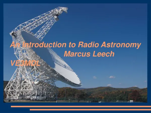
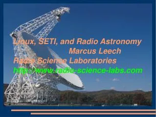
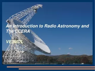
An Integrated 'Digital' Feed for 21cm Marcus Leech VE3MDL Science Radio Laboratories, Inc. Image appears courtesy NRAO/AUI. Out shoutings. Shouts out to: IRC gang Keenerd, DoYouKnow, mybit, LordKalma, atouk, RokLobsta, etc Mexican Crew: Deb 'n da chikkens Elvira and maybe Stan?.

E N D
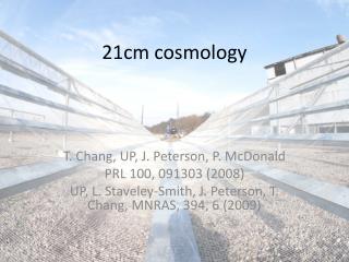
An Integrated 'Digital' Feed for 21cm Marcus Leech VE3MDL Science Radio Laboratories, Inc Image appears courtesy NRAO/AUI
Out shoutings Shouts out to: • IRC gang • Keenerd, DoYouKnow, mybit, LordKalma, atouk, RokLobsta, etc • Mexican Crew: • Deb 'n da chikkens • Elvira and maybe Stan?
Presentation Overview • Quicky introduction to Radio Astronomy • Description of the device • Why? • Challenges and solutions • A few preliminary results • Video “tour” of the device
What is Radio Astronomy? • Astronomy at wavelengths from a few mm to tens of meters • Visible light has wavelengths in the region of 500nm, that is, 5.0x10⁻⁷ meters • From a physics standpoint, there's no difference between visible light, and microwave/radio-wave “light”. • Living things have receptors for only a tiny part of the EM spectrum
Optical vs Radio Astronomy • Ability to resolve fine detail highly dependent on wavelength • A 10cm optical telescope can resolve details that would require a radio telescope over 42km in diameter at 21cm wavelength! • Sensitivity, however, is proportional to collecting area of the reflector, regardless of wavelength • Both use parabolic reflectors • Both must have a surface that is within 1/10th of a wavelength of a “perfect” parabola.
History of Radio Astronomy • Like much in science, it was discovered accidentally • Karl Jansky, 1933, working on sources of static on international radio-telephone circuits at wavelengths of 10-20m. • Discovered that static rose and fell with a period of 23 hours, 56 minutes. • Must be of celestial origin
History, continued • Built directional antenna • Pinpointed source at galactic centre, in Sagittarius
The Genesis of Radio Astronomy Science • Jansky was re-assigned to other projects after his work on radio-telephone “hiss”. • Several years went by with nobody understanding the significance of his discovery • Grote Reber picked up on Janskys work in 1937, building a 30ft dish in his back yard. • Eventually mapped entire Milky Way emission at 160MHz (1.8m wavelength) • Published in Astrophysical Journal in 1944 • Radio Astronomy now taken seriously
Grote Rebers Dish • Now preserved as historical artefact at NRAO, Green Bank, West Virginia
Rebers observations • 160 and 480MHz Skymap • Made by hand from dozens of chart recordings
Radio Astronomy Today • Radio Astronomy at the cutting-edge of astrophysical research • Roughly 70% of what we know today about the universe and its dynamics is due to radio astronomy observations, rather than optical observations • Big projects all over the world • VLA, New Mexico • Arecibo, Puerto Rico • GBT, Green Bank, West Virginia • Westerbork, Jodrell Bank, ALMA, Hat Creek, SKA, etc • Scientists named the basic flux unit after Karl Jansky • 1 Jansky == 10-26 watts/hz/meter2
How does the cosmos broadcast? • Multiple mechanisms for emissions • Blackbody radiation • Synchrotron radiation • Spectral lines from molecular and atomic gas clouds • Universe is more of a chemical “soup” than you'd guess from optical observations alone. RA lets you “see” the invisible. • Pulsar emissions • Maser emissions • Special case of molecular line emissions • Cosmic Microwave Background
Blackbody radiation • All objects that are warmer than 0K emit EM radiation over a wide spectrum • Warmer objects have higher peaks, at higher frequencies (shorter wavelengths)
Synchrotron radiation • Charged particles (e.g. electrons) accelerating through a magnetic field • Intensity higher at lower frequencies • Above 1GHz, synchrotron radiation very weak
Spectral Line Emissions • Many atomic and molecular species undergo emissions due to quantum phenomenon • Emission is spectrally pure: emitted at discrete frequencies, rather than a range of frequencies • Lots of really big gas clouds in interstellar space, and in star-forming regions within galaxies
The 21cm hydrogen line • Emission at 21.11cm wavelength (1420.40575MHz). • Van De Hulst proposed existence of neutral hydrogen in interstellar space in 1944. • Successfully detected in 1951 by Ewen and Purcell at Harvard, using very modest instrument • Confirmed weeks later by team in Netherlands headed by Jan Van Oort.
21cm line continued • Density of interstellar hydrogen very low • Less than 1 atom per cc of interstellar space! • Emission caused by collisional energy transfer, causing electron spin change in neutral hydrogen • A photon gets emitted at 21.11cm • For a given atom, “perfect” collision only happens about once every 100,000 to 1,000,000 years! • But along any given line of sight, there's a staggering amount of neutral hydrogen
Spectral lines and doppler effect • Existence of spectral emissions allows science to map velocities of gas clouds within and outside the galaxy: thermal and rotation component. • Doppler shift changes the observed wavelength/frequency of emission. • Just like approaching/receding train whistle • You can compute relative velocity by using the shifted wavelength and comparing to the “at rest” wavelength. • EXTREMELY IMPORTANT RESULTS
An experimental 21cm feed • Can an amateur-scale effort produce a “digitize at the feed” scheme for 21cm with acceptable performance? • Can differential radiometry techniques, previously studied by myself and Ken Tapping at 70cm and HF, be used at 21cm? http://www.sbrac.org/files/DTP_RX.pdf
System Design: Thermal • Analog RF components and receivers are attached to a thermal slab: 20cm x 20cm x 3cm T6 6061 aluminum. • LNAs firmly bolted to underside of slab, and covered. • Hopefully follow a common thermal “destiny” • Other parts also slab-attached: filters, line-amps, etc • Compute module is passively cooled • NO FANS!
System Design: Shielding • Slab forms top of shielded enclosure • Walls of 1mm 3003 aluminum sheet • Compute module and networking module attached to inside of walls • Power filtered going in and coming out of shielded environment • Ethernet connection via optical link • Backplate of circular waveguide feed forms bottom of enclosure. • Taped seams where necessary
System Design: Noise Source • Noise source, controlled by Compute Module • Provides roughly 6000K (13dB ENR) output • CAL pulses every 30 minutes, for 30 seconds • Simple 1N5235, 6.8V Zener. No amps required. • Lower noise levels required • 30K increase when CAL fires • Roughly same order as sky noise at 21cm • Very stable and repeatable
System Design: Ref. termination • Type-N 50-ohm terminator • Connected to thermal slab • Has extra thermal balast • Press fit into copper pipe • Copper pipe filled with pennies • REF with CAL pulses: quantitative results
System Design: Compute Module • Currently 1st-gen Odroid C1 • Quad-core S805 ARM-based SOC @ 1.5GHz • 1GB memory • USB, 1GiGe • GPIO • Passively cooled—bonded to skin and heatsink • Powered with linear-regulator array • Cheap 5V switchers seem to fail at 0.5 rated current • Eliminate PS switching noise
Preliminary Results: Spectral • In my driveway, with feed extension
Comparing Ewen/Purcell receiver • They spent about $5000.00 (2015 projected $), mine is under $500.00 • Aperture roughly 8 times larger than my “test” horn • Integration time O(hours) vs O(seconds) • Tsys ~3500K vs Tsys ~100K • Technology has come a long way, baby!
Next steps • More driveway testing • Test with optical ethernet • Still waiting on plumbing • Hopefully eliminate all spurs • Upgrade to B210 (or maybe dual B200mini) receiver • Will required XU4 upgrade as well • Build a “weather shell” for it, possibly with more shielding in the shell.