Download
1 / 10
110 likes | 308 Views
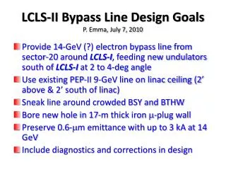
LCLS-II. bypass line. BC2. BC1. BP. BC2 bends normal (CSR on all bends). BC2 . CSR energy loss steers beam. BP. BC2 . BC2 bends reversed (CSR on all bends). CSR energy loss steers beam. BC2 bends normal (CSR on all bends). ge x = 2.6 m m. ge y = 1.4 m m.

E N D
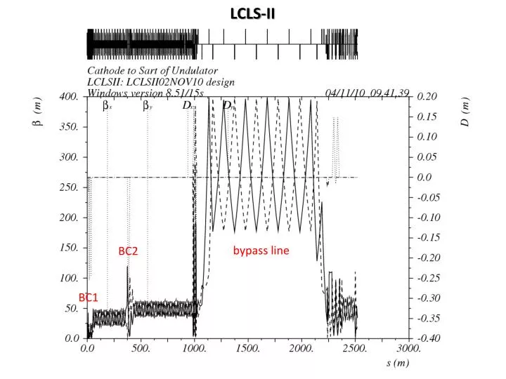
LCLS-II bypass line BC2 BC1
BP BC2 bends normal (CSR on all bends) BC2 CSR energy loss steers beam BP BC2 BC2 bends reversed (CSR on all bends) CSR energy loss steers beam
BC2 bends normal (CSR on all bends) gex= 2.6 mm gey= 1.4 mm BC2 bends reversed (CSR on all bends) gex= 1.6 mm gey= 1.5 mm
After BP-DL After BC2 gex= 2.6 mm BC2 bends normal (CSR on all bends) After BP-DL After BC2 gex= 1.6 mm BC2 bends reversed (CSR on all bends)
Over-Compress in BC1? Under-Compression in BC1 3 kA Over-Compression in BC1 3 kA
BC1 CSR Emittance Growth data from K. Bane et al., Phys. Rev. ST Accel. Beams 12, 030704 (2009)
RF Sections for LCLS-II E1 = 250 MeV E2 = 4.2 GeV j2-40° 4 4 1 2 4 5 6 7 8 1 2 3 4 5 6 7 8 1 2 3 4 5 6 7 8 1 2 3 11 BC1 BC2 11 12 13 14 E3 13.5 GeV j3 = 0 TCAV3 (klys. 14-6) 7 8 1 2 3 4 5 6 7 8 1 2 3 4 5 6 7 8 1 2 3 4 5 6 7 8 1 2 3 4 5 6 7 8 1 2 3 4 5 6 7 8 1 2 3 4 15 16 17 18 19 20 14 no RF • 13.5 GeV available if 20-1,2,3,4 are restored • 12.6 GeV available if not • Another 0.22 GeV available with 19-7 restored (no e+)
RF Modification for LCLS-II on the Linac Beamline • 11-1b and 11-1c sections will be cut down from 10’ sections to 9.4’. • 11-2a, b, c, and d sections will be removed to install BC1. • 11-2 modulator will be modified and used to power L1X. • 11-3a section is not installed and will remain that way. • 11-3b & c e+ capture sections will be replaced with standard 10’ sections. • 11-3d section is not installed, but will be reinstalled. • 13-5d, 13-7d, 14-1d, and 14-3d will each be replaced by a 9.4’ (4 new wire scanners). • All 8 sections at 14-5 and 14-6 will be removed to install BC2. • 14-5 klystron and modulator will not be used. • 14-6 klystron and modulator will be used to power TCAV3b at 14-8d. • 14-7a section will be removed to make room for post-BC2 matching quadrupoles. • 14-8d section will be removed to make room for TCAV3b. • 15-1d section will be removed to make room for BXKIKb. • 15-6d section will be replaced by a 7’ section to make room for OTR_TCAV screen. • The 4 sections at 19-7 are not installed (SLCe+ source) and will not (?) be re-installed. • None of the 16 sections in 20-1, 20-2, 20-3, 20-4 are installed but will be re-installed. (The four 20-1 sections were not present even prior to FACET.)
Sector 19 & 20 RF Modification for LCLS-II • 19-7 needs a modulator, klystron, and all waveguide, plus it eliminates e+ • All 16 ten-foot RF structures are missing at 20-1, 2, 3, & 4 (0.9 GeV) • 20-1 needs a modulator, klystron, and all waveguide (penetrations too full?) • 20-2 needs all new FACET racks removed*, a modulator, klystron, and all waveguide • 20-3 needs a klystron (% modulator 120-V power restored) • 20-4 needs a klystron (% modulator 120-V power restored) * 25 k$ estimate to remove sec-20 FACET equipment (Rafael Fernando Da Silva, Nov. 11, 2010)
74 m 72 m 16 GW 14 GW