Download
1 / 41
470 likes | 896 Views
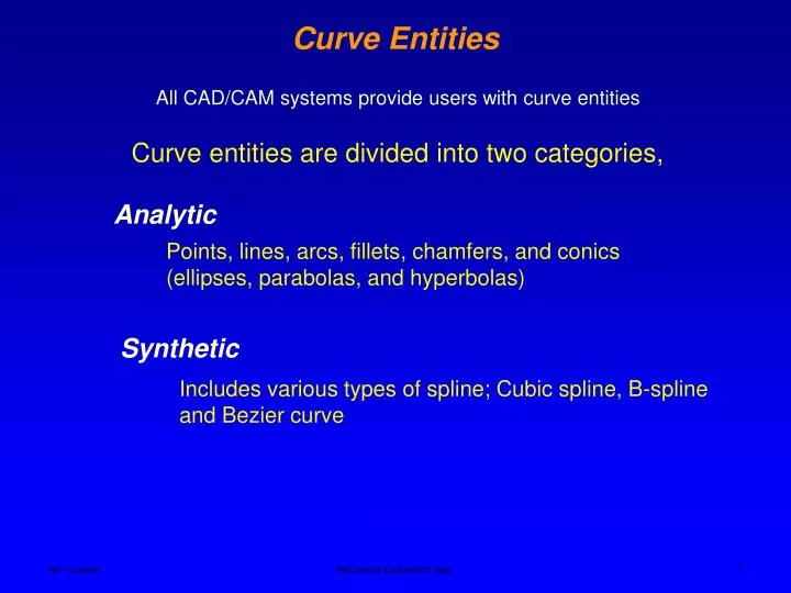
Analytic. Points, lines, arcs, fillets, chamfers, and conics (ellipses, parabolas, and hyperbolas). Synthetic. Includes various types of spline; Cubic spline, B-spline and Bezier curve. Curve Entities. All CAD/CAM systems provide users with curve entities.

E N D
Analytic Points, lines, arcs, fillets, chamfers, and conics (ellipses, parabolas, and hyperbolas) Synthetic Includes various types of spline; Cubic spline, B-spline and Bezier curve Curve Entities All CAD/CAM systems provide users with curve entities Curve entities are divided into two categories, Mechanical Engineering Dept.
A parabola is the curve created when a plane intersects a right circular cone parallel to the side (elements) of the cone Cutting plane Parallel Conic Curves - Parabolas Conic curves or conics are the curves formed by the intersection of a plane with a right circular cone (parabola, hyperbola and sphere). Mechanical Engineering Dept.
Zero g Parabola Parabola Zero g Zero g Load Beam of uniform strength Weightless flight trajectory A parabola revolved about its axis creates a surface called paraboloid. An auditorium ceiling in shape of paraboloid reduces reverberations if the speaker stands near the focus Conic Curves - Parabolas Light rays Light rays Applications of parabola Light source Eye piece Searchlight mirror Telescope mirror Mechanical Engineering Dept.
Conic Curves - Hyperbolas A hyperbola is the curve created when a plane parallel to the axis and perpendicular to the base intersects a right circular cone. Element (side) Hyperbola Orthographic view Mechanical Engineering Dept.
Dulles Airport, designed by Eero Saarinen, is in the shape of a hyperbolic paraboloid Conic Curves - Hyperbolas Cooling Towers of Nuclear Reactors The hyperboloid is the design standard for all nuclearcooling towers. It is structurally sound and can be built with straight steel beams. For a given diameter and height of a tower and a given strength, this shape requires less material than any other form. Mechanical Engineering Dept.
Conic Curves - Ellipse An ellipse is the curve created when a plane cuts all the elements (sides) of the cone but its not perpendicular to the axis. Mechanical Engineering Dept.
The Statuary Hall in the Rotunda (Capitol Building in Washington D.C.) has a ceiling curved as an ellipse. It has been suggested that after John Quincy Adams left presidency and became a member of the House, he would sit in one focus point of the ellipsoid and listen to the other party located near the other focus point. The place is labeled in the floor by a brass name tag. Conic Curves - Ellipse In New York's Grand Central Station, underneath the main concourse there’s a special place known as The Whispering Gallery where the faintest murmur can be heard 40 feet away across the busy passageway. Look for a place where two walkways intersect, and a vaulted roof forms a shallow dome. Take a friend and pick diagonal corners. Turn your faces to the wall and start talking. It's a popular spot for marriage proposals. Other famous examples are found in Mormon Tabernacle in Salt Lake, St Paul's Cathedral in London and St Peter's Basilica in Rome. Mechanical Engineering Dept.
Elliptical gears are used for certain applications Conic Curves - Ellipse Some tanks are in fact elliptical (not circular) in cross section. This gives them a high capacity, but with a lower center-of-gravity. They're shorter, so that they can pass under a low bridge. You might see these tanks transporting heating oil or gasoline on the highway Ellipses (or half-ellipses) are sometimes used as fins, or airfoils in structures that move through the air. The elliptical shape reduces drag. On a bicycle, you might find a chainwheel (the gear that is connected to the pedal cranks) that is approximately elliptical in shape. Here the difference between the major and minor axes of the ellipse is used to account for differences in the speed and force applied Mechanical Engineering Dept.
Conic Curves Mechanical Engineering Dept.
Curve Entities – Synthetic Curves Analytical curves are usually not sufficient to meet the design requirements of complex mechanical parts, car bodies, ship hulls, airplane fuselages and wings, shoe insoles, propeller blades, bottles, plastic enclosures for household appliances and power tools, …. Mechanical Engineering Dept.
Coffee Press Radio Thermos Mechanical Engineering Dept.
Cubic spline Bezier curve B-spline curve Synthetic Curves – Freeform Curves For CAD systems, three types of freeform curves have been developed, Mechanical Engineering Dept.
Synthetic Curves – Bezier Curve • The data points of the Bezier curve are called control points. Only the first and the last control points lie on the curve. The other points define the shape of the curve. • The curve is always tangent to the first and the last polygon segment. The curve shape tends to follow the polygon shape. Characteristic polygon Mechanical Engineering Dept.
Modifying the curve by keeping the polygon fixed and specifying multiple coincident points at a vertex (control point) Synthetic Curves – Bezier Curve Modifying the curve by changing one or more vertices of its polygon (control points). Mechanical Engineering Dept.
Synthetic Curves – Bezier Curve A desired feature of the Bezier curve or any curve defined by a polygon is the convex hull property. This property guarantees that curve lies in the convex hull regardless of changes made in control points. • The curve never oscillates wildly away its defining control points • The size of the convex hull is the upper bound on the size of the curve itself. Mechanical Engineering Dept.
Bezier curve Cubic curve Synthetic Curves – Bezier Curve Disadvantages of Bezier curve over the cubic spline curve • The curve lacks local control, if one control is changed, the whole curve changes (global control) • The curve degree depends on the number of data points, most CAD software limit the number of points used to define a Bezier curve Mechanical Engineering Dept.
Synthetic Curves – Bezier Curve The designer should be able to predict the shape of the curve once its control points are given. Mechanical Engineering Dept.
Synthetic Curves – Bezier Curve Mechanical Engineering Dept.
Synthetic Curves – B-Spline Curve B-spline curves are powerful generalization of Bezier curve. • The curves have the same characteristics as Bezier curves • They provide local control as opposed to the global control of the curve by using blending functions which provides local influence. • The B-spline curves also provide the ability to separate the curve degree from the number of data points. Mechanical Engineering Dept.
Synthetic Curves – B-Spline Curve Local control of B-spline curve Mechanical Engineering Dept.
As the degree decreases, the generated B-spline curve moves closer to its control polyline. 3 degree 7 degree 5 degree Synthetic Curves – B-Spline Curve Effect of the degree of B-spline curve on the shape Tangent to the curve at the midpoints of all the internal polygon segments Mechanical Engineering Dept.
Synthetic Curves – B-Spline Curve Effect of point multiplicity of B-spline curve on the shape Multiple control points induce regions of high curvature, increase the number of multiplicity to pull the curve towards the control point (3 points at P3) Mechanical Engineering Dept.
SolidWorks Commands – Parabola and Spline Mechanical Engineering Dept.
2 - Select the Apex 1 - Select the Focus point Start End 3 - Select the Start point, and drag to the End point Parabola Command in SW Parabola Start End Focus Vertex Mechanical Engineering Dept.
Data point #2 Point #2 modified Point # X & Y coordinates of the point Spline Command in SW B-Spline Curve using interpolation – SolidWorks generates a smooth curve passing through all data points Mechanical Engineering Dept.
Size (weight) angle Spline Command in SW The spline shape can be modified by manipulating the tangent vector for each point. Data point #3 is selected Mechanical Engineering Dept.
Spline Toolbar in SW Mechanical Engineering Dept.
Spline in NX5 (Unigraphics) All splines created in NX are Non Uniform Rational B-splines (NURBS). In NX the terms "B-spline" and "spline" are used interchangeably. Splines Mechanical Engineering Dept.
Studio Spline Use this command to interactively create an associative or non-associative spline. You can create splines by dragging defining points or poles. You can assign slope or curvature constraints at given defining points or to end poles. Making splines associative preserves their creation parameters and links them parametrically to parent features Spline in NX5 (Unigraphics) Mechanical Engineering Dept.
Change Curvature Change Tangent Direction Change Tangent Magnitude Spline in NX5 (Unigraphics) Manipulating the spline curve Mechanical Engineering Dept.
Open option Spline in NX5 (Unigraphics) B-Spline Curve, extrapolation method(does not pass thru points) Closed option Mechanical Engineering Dept.
This option lets you create a spline by fitting it to specified data points. The data points can reside in a set of chained points, or on faceted bodies, curves, or faces. You can set endpoint and inner continuity constraints, and you can control the accuracy and shape of the fit by specifying: Spline in NX5 (Unigraphics) Fit Spline • degrees and segments • degrees and tolerance • a template curve Mechanical Engineering Dept.
Five data points using 4th order polynomial to fit A Fit Spline created on a faceted Body Example - Spline in NX5 (Unigraphics) Five data points using 3rd order polynomial to fit Mechanical Engineering Dept.
Parabola Command in NX A parabola is a set of points equidistant from a point (the focus) and a line (the directrix), lying in a plane parallel to the work plane. The default parabola is constructed with its axis of symmetry parallel to the XC axis. To create a parabola: Indicate the vertex for the parabola using the Point Constructor. Define the creation parameters of the parabola. Mechanical Engineering Dept.
Example - Parabola Command in NX Mechanical Engineering Dept.
Hyperbola Command in NX This option allows you to create a hyperbola. By definition, a hyperbola contains two curves - one on either side of its center. In NX, only one of these curves is constructed. The center lies at the intersection of the asymptotes and the axis of symmetry passes through this intersection. The hyperbola is rotated from the positive XC axis about the center and lies in a plane parallel to the XC-YC plane. To create a hyperbola: Indicate the center of the hyperbola using Point Constructor. Define the parameters of the hyperbola. A hyperbola has two axes: a transverse axis and a conjugate axis. The semi-transverse and semi-conjugate parameters refer to half the length of these axes. The relationship between these two axes determines the slope of the curve. Mechanical Engineering Dept.
Example - Hyperbola Command in NX Hyperbola Revolved feature Mechanical Engineering Dept.
The General Conic option lets you create conic sections by using either one of the various loft conic methods or the general conic equation. The resulting conic is either a circle, an ellipse, a parabola, or a hyperbola, depending on the mathematical results of the input data. General Conic Curve Command in NX Overview of Conics Conics are created mathematically by sectioning cones. The type of curve that results from the section depends on the angle at which the section passes through the cone. A conic curve is located with its center at the point you specify, in a plane parallel to the work plane (the XC-YC plane). Mechanical Engineering Dept.
Revolved feature Example - Hyperbola Command in NX This option lets you create a conic section by defining five coplanar points. Define the points using the Point Constructor. If the conic section created is an arc, an ellipse, or a parabola, it will pass through the points starting at the first point and ending at the fifth. Mechanical Engineering Dept.