Download
1 / 29
310 likes | 516 Views
Deferred Decision Making Enabled Fixed-Outline Floorplanner. Jackey Z. Yan and Chris Chu. DAC 2008. Outline. Introduction Generalized slicing tree Enumerative packing Block swapping and mirroring Overview of the algorithm Experimental results Conclusion. Introduction.

E N D
Deferred Decision Making Enabled Fixed-Outline Floorplanner Jackey Z. Yan and Chris Chu DAC 2008
Outline • Introduction • Generalized slicing tree • Enumerative packing • Block swapping and mirroring • Overview of the algorithm • Experimental results • Conclusion
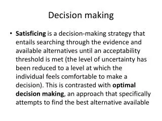
Introduction • Floorplanning has become a very crucial step in modern VLSI designs. • A good floorplan solution definitely has a positive impact on the placement, routing and even manufacturing. • Fixed-outline floorplanning has been shown to be much more difficult, compared with classical outline-free floorplanning.
Introduction • This paper presents a fast, high-quality fixed-outline floorplanner called DeFer. • It can handle both hard and soft modules. • Deferring the decisions on these four factors: • Subfloorplan Orientation • Subfloorplan Order • Slice Line Direction • Slicing Tree Structure • Traditional SA based approaches specify these factors at an early step.
Generalized slicing tree • An ordinary slicing tree The parent tree node of two child subfloorplans A and B can be labeled ‘H’(‘V’) to specify that A and B are separated by a horizontal(vertical) slice line.
Generalized slicing tree • A new operator: ⊕ to incorporate both ‘H’ and ‘V’ slice line directions. • Do not differentiate the ‘top-bottom’ or ‘left-right’ order between the two child subfloorplans any more.
Generalized slicing tree • The decisions on Subfloorplan Orientation, Subfloorplan Order and Slice Line Direction are deferred. • Each parent node in the slicing tree represents all 16 slicing layouts between two child subfloorplans.
Generalized slicing tree • Each subfloorplan layout property is captured by its associated shape curve. • Develop three steps to combine two child curves A and B into one parent curve C.
Generalized slicing tree • Given two child shape curves corresponding to two child subfloorplan, the new operations can be applied to combine these two curves into one parent curve. • Considering the trade-off between runtime and solution quality, DeFer keeps at most 1000 points for each shape curve.
Enumerative packing • Enumerate all slicing tree structures and then enumerate all permutations of the modules. • The complete slicing tree structures for 3 to 6 modules:
Enumerative packing • For each slicing tree structure, different permutations of the modules should also be considered. • For example, in tree T4a: • Four modules A, B, C, D can be mapped to leaves 1-2-3-4. • Order A-B-C-D and A-C-B-D derive two different layouts • But order A-B-C-D and B-A-C-D are the same in T4a.
Enumerative packing After pruning such redundancy, we have 12 non-redundant permutations in T4a, 3 in T4b. A-B-C-D B-C-A-D A-B-D-C B-C-D-A A-C-B-D B-D-A-C A-C-D-B B-D-C-A A-D-B-C C-D-A-B A-D-C-B C-D-B-A A-B-C-D A-C-B-D A-D-B-C
Enumerative packing • The curves from all slicing tree structures are merged into one curve that captures all possible slicing layouts.
Enumeration by Dynamic Programming • The shape curve for a set of modules can be defined recursively by: • S(M) is a shape curve capturing all slicing layouts among modules M, MERGE() operates on shape curves from different sets. • The previously generated curves can be reused for building up the curves of larger subsets of modules, many redundant computations are eliminated.
Extension of EP at High-Level • For example, after the partitioning step, subcircuit A contains a big hard macro. • No matter how hard EP explores various packing layouts within A or B, there is always a large deadspace Q.
Extension of EP at High-Level • Apply EP on a set of subfloorplans. • If the total area of big hard macros in one subfloorplan is more than 55% of this subfloorplan area, DeFer would apply EP to further explore the various slicing tree structures of that subfloorplan.
Block swapping and mirroring • Rough swapping: treat all internal modules to be at the center of their subfloorplan outline in calculating the HPWL. • Detailed swapping: use the actual center coordinates of each module in calculating the HPWL. • Mirroring
Block swapping and mirroring • The importance of Rough swapping: • Try to swap two subfloorplans A and B • Modules C and D are highly connected by netcd. • The coordinates of C and D are still unknown.
Block swapping and mirroring • If we randomly specify the positions of C and D in (a), then we may swap A and B to gain better wirelength. • If C and D are specified in the positions in (b), then we may not swap them. • The best is to assume C, D and all modules inside subfloorplans A and B are at the centers of A and B, such that the right decision can be made based on neto. • First apply Rough swapping from top-down, followed by Detailed swapping and Mirroring to further optimize the wirelength.
Overview of the algorithm • DeFer has five steps: • 1. Partitioning Step • 2. Combining Step • 3. Back-tracing Step • 4. Swapping Step • 5. Compacting Step
Overview of the algorithm • 1. Partitioning Step: • Divide one original circuit into several small subcircuits. • hMetis is called to perform a recursive bi-sectioning on the circuit, until every subcircuit contains less than or equal to maxN modules. • maxN=10 by default.
Overview of the algorithm • 2. Combining Step: • Apply the Enumerative Packing to explore all slicing packing layouts within the subcircuit. • An associated shape curve representing these possible layouts for each subcircuit is produced. • DeFer traverses from bottom-up constructing a shape curve for every tree node.
Overview of the algorithm • 3. Back-tracing Step: • Once the final shape curve is available, choose the points fitting into the fixed outline. • DeFer chooses K points at most (K=11 by default). • If m>K, K points are chosen. • If 0<m<=K, all m points are chosen. • If m=0, DeFer still chooses at most K points near the upper-right corner of the fixed outline, but try to compact them into the fixed outline in Step 5. • Back-tracing can be propagated from the top to the bottom level. m points
Overview of the algorithm • 4. Swapping Step: • Make decisions on the subfloorplan order. • Rough Swapping • Detailed Swapping • Mirroring The left-right or top-bottom order of two child subfloorplans would not change the dimension of their parent floorplan outline, but it may improve the interconnections.
Overview of the algorithm • 5. Compacting Step: • Compacting all modules to the center of the fixed outline, such that the wirelength is further reduced. • If previous floorplan is outside of the fixed outline, instead of compacting to the center, DeFer compacts them to the lower-left corner. • If it still fails, then DeFer would restart from Step 1, try another run. By default DeFer attempts 5 runs at most.
Conclusion • This paper proposed a fast, high-quality fixed-outline floorplanner DeFer. • DeFer over-performs all other state-of-the-art floorplanners in every aspect. • In the future, DeFer can be integrated into placement tools to handle large-scale mixed-size designs.