Download
1 / 19
190 likes | 199 Views
This document provides a detailed analysis of landing gear placement, design, and weight assessment for an aircraft. It includes guidelines for safe and strong landing gear design, as well as calculations for the required cross-sectional area of the front gear bolt. The analysis also considers the energy absorption capabilities of the landing gear bungee.

E N D
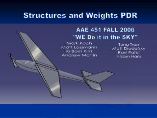
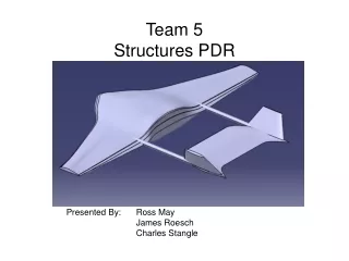
Structures PDR #2 AAE451 – Team 3 December 2, 2003 Brian Chesko Brian Hronchek Ted Light Doug Mousseau Brent Robbins Emil Tchilian
Introduction • Walk Around • Landing Gear Placement • Landing Gear Design • Landing Gear Analysis • Updated Weight Assessment
Aircraft Walk Around Wing Span = 14.4 ft Wing Chord = 2.9 ft A/C Length = 10 ft T-Tail – NACA 0012 Pusher Internal Pod Tricycle Gear Low wing – Clark Y
Landing Gear Placement (I) θ = tipback angle = Landing gear placement based on guidelines found in Raymer
Landing Gear Placement (II) γ = overturn angle = Landing gear placement based on guidelines found in Raymer
Landing Gear Design • Safe and Strong • Aluminum for structure • Rubber bungee to absorb energy • Do not break airplane if gear fails • Easy to Construct • Weldable (the aluminum, not the bungee) • Easily Obtainable
Easily Obtainable Square Tubing Ref. www.mcmaster.com
Buckling of Rear Gear Load Ref. Gere pg. 763 L Where L = Length (in) E = Young’s Modulus (psi) I = Moment of Inertia (in4) A = Cross Sectional Area (in2) Load Assumptions: Pinned-Pinned Column 1st Mode Buckling No Eccentricity For Rear Gear: L ~ 15.3 in
Compressive Failure of Rear Gear Load L Ref. MIL-HDBK-5H: 3-255 Where Load = (Weight)(S.F.)(Gloading) A = Cross Sectional Area (in2) Load Assumptions: Weight = 53 lbf Gloading = 10 S.F. = 1.5 Aluminum 6061-T6 No Buckling
Stress on Rear Gear Smallest easily obtainable tubing: 1” x 1” x 0.062” t=0.062” t=0.125”
Great, what about the bungee? • Consider worst reasonable landing situation • Moving at (1.1)Vstall • 5 feet above ground • Aircraft falls out of the sky • Can the bungee absorb the energy associated with this landing?
Great, what about the bungee? Assumptions: Weight = 53 lbf Vstall = 30 ft/sec Altitude = 5 ft Don’t want x to exceed 3 inches (beyond initial stretch) on landing
What Spring Constant is Needed? Required k ~ 3.75 lbf/in 1/k ~ 0.266 in/lbf
What is the Spring Constant? Relaxed Length ~18 inches
Front Gear Design Aluminum Bolt • Provides pivot for gear (does not break) Nylon Bolt • Breaks during hard landing Front Gear • Designed not to break • Designed not to bend
How Big is the Bolt? Ref. Gere pg 900 Load If load = (Weight)(S.F.)(Gloading) = 795 lbf Reaction = 1770 lbf (instantaneous) Need cross sectional area of bolt to be 0.197 in2 Diameter of nylon bolt = 0.5 in Reaction Assumptions: Weight = 53 lbf Gloading = 10 S.F. = 1.5 6.9” 3.1”