Download
1 / 18
180 likes | 189 Views
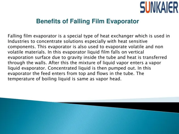
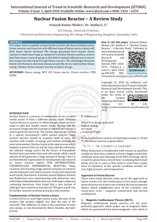
This study focuses on the design and performance of a cascade-type first wall (FW) in a laser-fusion reactor. The cascade design allows for efficient cooling and control of the falling liquid film flow. Numerical simulations and experiments were conducted to evaluate the stability and performance of the liquid film flow.

E N D
Falling Liquid Film Flow along Cascade-type First Wall of Laser-Fusion Reactor T. Kunugi, T. Nakai, Z. Kawara Department of Nuclear Engineering Kyoto University, Japan Collaborated with T. Norimatsu ILE Osaka University, Japan Lijiang river 10.24.2007
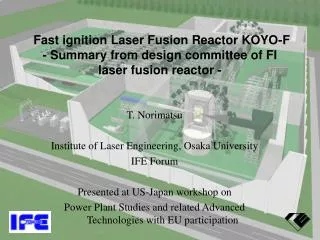
Design specification of KOYO-Fast • Net output 1200 MWe (300 MWe x 4) • Reactor module net output 300 MWe • Laser energy 1.2MJ • Target gain 167 • Fusion pulse out put 200 MJ • Reactor pulse rep-rate 4 Hz • Reactor module fusion outputr 800 MWth • Blanket energy multiplication 1.13 • Reactor thermal output 904 MWth • Total plant thermal output 3616 MWth (904 MWth x 4 ) • Thermal electric efficiency 42 %(LiPb Temperature ~500 C) • Total electric output 1519 MWe • laser efficiency 8.5% (implosion) , 5% (heating) • Laser pulse rep-rat 16 Hz • Laser recirculating power 240 MWe(1.2 MJ x 16 Hz / 0.08) • Net plant out put power 1200 MWe(1519MWe - 240MWe - 79MWe Aux.) • Total plant efficiency 33.2 %( 1200 MWe/ 3616 MWth)
Basic design concept for PbLi chamber • No pressurized pipe or vessel in the chamber for avoiding high pressure in chamber in accidents, and for achieving simple maintenance and long life use. • Free surface fast cooling using divergent flow thorough from bulk flow (small holes or slit structure ⇒ Cascade-typed FW) • Feritic steal is used for cylindrical vessel and upper dome cover vessel • SiC/SiC is used as separate wall without pressure bulkhead • Adjusting holes or slits on the separate to control divergent flow for stabilizing and fast cooling free surface (200ms for renewal of FW) • Two layers PbLi blankets (~20 cm for free surface first wall and ~80 cm for blanket) and ~45cm graphite neutron reflector. SiC wall FeriticSteal PbLi C PbLi 50 mm 450 mm 800 mm 200 mm
Cascade-typed FW Concept LiPb Flow Graphite 45 cm SiC/SiC porous wall container The coolant flows downward along FW → into reservoir behind FW → flowslaterally to a slit → goes upward into the slit → past the exit of the slit → some of the overflowed coolant forms a falling liquid-film flow Ablation control by FW inclination Free-surface flow control by cascade passage
KOYO reactor cross-sectional view LiPb flow inlet (280-300oC) Reflector Gas coolant outlet Laser fusion modular power plant "KOYO" design, which has four reactor chambers driven by one laser system, was proposed . Gas coolant inlet Cascade typed Liquid wall LiPb flow outlet(480-500oC) KOYO laser-fusion reactor
Thermal flow of KOYO-F( One module) 300 MWe 200MJ /shot x 4Hz hther-elec=30%
Cascade-typed Liquid Wall Redesigned Cascade-typed liquid wall 30cm Mixing is not sufficiency Surface temperature rises As a result, the fluid does not mix well, and the surface temperature of the first wall is continuously rising. Some flow resistances to maintain the surface shape. Difficult to keep thickness of liquid film Primary design proposal The fluid covering the surface heated at the upper unit does not enter the backside of FW. Making space between reservoir units ⇒ static pressure drop for each units could be kept constant The height of the first wall of each unit is set to 30cm corresponding to the surface renewal time: 4 Hz laser repetition
Proof-of-principle experiment • The flow visualization experiment was performed as a POP experiment. • In order to examine the performance of the new cascade-typed FW concept, numerical simulation was performed using STREAM code with k-e turbulent model.
Similarity Law and Flow Condition of Visualization Test In the actual reactor, Li17Pb83will be working fluid and SiC/SiC composite material will be used for the first wall. In this case, the wall surface might have a lower wettability. In the present experiment, we used the acrylic resin board as the FW because of its lower wettability. The major concern of this experiment is to know the stability feature of the liquid film flow, therefore, the Weber number is the key parameter ,where is based on the film thickness , velocity , density , and surface tension coefficient . According to the similarity law, we can estimate the flow velocity ratio. Water: =7.275×10⁻²[N/m] =9.98×10² [kg/m3] Li17Pb83: =4.80×10⁻¹[N/m] =9.6×10³ [kg/m3]
Experimental Setup Valve Flow Meter Valve Flow Meter Valve Tank Valve Pump Pump Tank Drain Drain Electric Balance Flow Condition Re:4800~9600 T=17.5[。c]
Experimental results The average flow velocity is 1.75 times (14 l/min) of Weber number coincident condition (8.0 l/min) with the actual reactor. Overflow • At the overflow regions, there are many small waves. • The liquid-droplet generation from the liquid surface and the large wave on the liquid-film surface were not observed. • These small waves might trigger free surface unstable motion of the falling liquid-film flow on FW. Liquid Film Flow
Break-up of FW liquid film The averaged flow velocity is 0.75 times (6.0 l/min) of Weber number coincident condition (8.0 l/min) with an actual reactor condition. Film Break-up Film Break-up
Numerical Simulation We performed the two-dimensional thermo-fluid simulation by using the MARS function of the STREAM (commercial 3-D thermo- fluid code, Software Cradle Co. Ltd. in Japan). 3mm Experiment Flow Direction Numerical Simulation Liquid Film Flow Overflow
Comparison between Exp. & CFD 3mm 3mm Computational Conditions Mesh:782800 Fluid1:Air Fluid2:Water Material:Acrylic resin Re=5806, T=20.0[。c] Experiment Numerical Simulation
Comparison between Water and LiPb Li17Pb83/SiC Water/Acrylic plate
Comparison between Water and LiPb Water/Acrylic plate Li17Pb83/SiC
Conclusions We proposed the cascade typed liquid wall concept, and conducted the POP experiments and the numerical simulation (CFD) based on the consideration of the similarity law. The CFD result qualitatively agreed with the POP flow visualization experiment, so that the cascade-typed liquid film system will be realized. We also confirmed that the stable liquid film with sufficient thickness (liquid wall covering the first wall) could be naturally formed. Therefore, it seems that this liquid wall concept might be possible to apply to the real reactor.