Download
1 / 37
430 likes | 904 Views
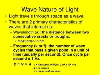
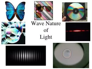
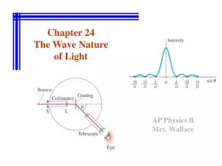
Wave Nature of Light. AP Physics B Chapter 24 Notes. Wave Theory. Huygens supported the wave theory of light, and developed a principle that says every point on a wave can be thought of as a mini-wave that all spread out at the same speed and are enveloped by a new wave front. Wave Theory.

E N D
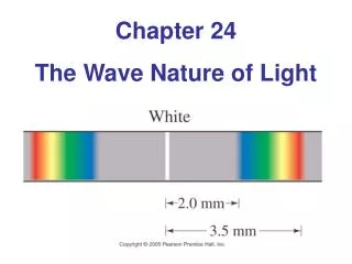
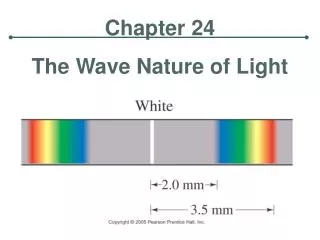
Wave Nature of Light AP Physics B Chapter 24 Notes
Wave Theory Huygens supported the wave theory of light, and developed a principle that says every point on a wave can be thought of as a mini-wave that all spread out at the same speed and are enveloped by a new wave front
Wave Theory This principle is consistent with the phenomenon of diffraction—the bending of waves into the “shadow” region behind an obstacle
Wave Theory Refraction can also be explained by Huygens’ Principle. When light changes media, v andλchange but f does not. So
Diffraction—Superposition Review Recall what can happen when two waves run into each other—constructive or destructive interference. In phase Out of phase
Diffraction—Interference Patterns When light OR sound is produced by TWO sources a pattern results as a result of interference.
Diffraction—Double Slit If a wave is of monochromatic light (single wavelength) it should produce an interference pattern. Young conducted just such an experiment…and in fact did see such a pattern
Double Slit Diffraction Pattern Figure 2 Figure 1 Here is the pattern you will see. Notice in figure 2 that there are several bright spots and dark areas in between. The spot in the middle is the BRIGHTEST and thus the CENTRAL MAXIMUM. We call these spots FRINGES. The intensity of the light decreases as you move away from the central bright spot—these are called ORDERS away from the center.
Diffraction – Orders, m We use the letter, m, to represent the ORDER of the fringe from the bright central. Second Order Bright Fringe m = 2 Second Order Bright Fringe m = 2 First Order Bright Fringe m = 1 First Order Bright Fringe m = 1 Central Maximum It is important to understand that we see these bright fringes as a result of CONSTRUCTIVE INTERFERENCE.
Diffraction—Pattern Explained If two waves enter each slit, they will meet at the screen having travelled the same distance. They will be in phase and create a central maxima (bright spot).
Diffraction—Pattern Explained Now consider two diffracted waves moving at an angle θ. The blue wave will travel an additional λ compared to the red wave, so they will constructively interfere at the screen. Another bright spot
Diffraction –Path Difference Explained Notice that these 2 waves are IN PHASE. When they hit they screen they both hit at the same relative position, at the bottom of a crest. How much farther did the red wave have to travel? Exactly – ONE WAVELENGTH l The call this extra distance the PATH DIFFERENCE. The path difference and the ORDER of a fringe help to form a pattern.
Diffraction—Pattern Explained Now consider two diffracted waves moving at another angle θ. The blue wave will travel an additional 1/2λ compared to the red wave, so they will destructively interfere at the screen. A dark spot
Diffraction –Path Difference Explained Notice that these 2 waves are OUT OF PHASE. When they hit they screen they both hit at the different relative positions, one at the bottom of a crest and the other coming out of a trough, causing destructive interference. How much farther did the red wave have to travel? Exactly – ONE HALF OF A WAVELENGTH 0.5 l This PATH DIFFERENCE and the ORDER of a fringe help to form another pattern.
Path Difference Redux Simple geometry tells us that the path difference is equal to: d sinθ
Diffraction Calculations We already determined the path difference was λ for constructive interference and 1/2λ for destructive interference, so for all integers m: d sinθ=mλd sinθ=(m+ ½)λ
Diffraction Calculations Suppose we have 2 slits separated by a distance, d and a distance L from a screen. Let point P be a bright fringe. We can find the angle q using tanq= y/L This can be used in our calculations or if q is small enough sinq≈tanq≈ q But q must be in radians! P y q d B.C. L
Double Slit Example A viewing screen is separated from a double slit source by 1.2 m. The distance between the two slits is 0.030 mm. The second -order bright fringe ( m=2) is 4.5 cm from the central maximum. Determine the wavelength of light.
Diffraction Summary The diffraction pattern gives a nice smooth interference pattern between maxima and minima
Visible Spectrum and Dispersion Intensity of light is related to the energy carried (proportional to A2). Color of light is related to f and λ (recall c=fλ) Visible light ranges from 400 nm (below is UV) to 750 nm above is (IR) Blue/UV have higher fthan red/IR.
Visible Spectrum and Dispersion A prism separates light into a rainbow because the index of refraction for a material depends on λ.
Visible Spectrum and Dispersion Another nice benefit is the rainbow, which occurs because of dispersion inside a water drop (so how special are double rainbows!?)
Diffraction by a Single Slit Double slit interference seems reasonable, but diffraction patterns caused by single slits are less intuitive…but its effects were predicted by Poisson
Diffraction by a Single Slit The diffraction of waves will cause bright(ish) bands as the angle of diffraction increases so PD is 3/2, 5/2, … longer for the top rays. The central maxima is brightest by far.
Diffraction by a Single Slit The dark bands (minima) are found by: Dsinθ=mλ Where D is the slit width and θ is one half the angular width of the central maxima
Single Slit Example P. 22, pg, 693 How wide is the central diffraction peak on a screen 2.30 m behind a 0.0348 mm-wide slit illuminated by 589 nm light?
Diffraction Gratings Diffraction gratings have many slits—light will constructively interfere at an angle θ that makes a PD of Δl=mλ. This creates an interference pattern maxima given by: dsinθ=mλ Maxima are sharper and narrower than with double slit.
Thin Film Interference Another way interference can be seen is in thin films (must be order of few λ thick)—light reflected off top and bottom layers will interfere
Thin Film Interference Reflected light wave exhibit the same behavior as mechanical waves—they are inverted when travelling from faster to slower media (n1< n2), upright when n2< n1 This is key to understanding the interference
Constructive Thin Film Interference If the thickness of the film is 1/4λ then PD is 1/2λ which constructively interferes with the reflected ray
Thin Film Interference Generally, for constructive interference to occur film thickness, t, needs to be: 2t=(m + ½)λn or2nt=(m + ½)λ Destructive interference occurs at thickness: 2t=(m)λn or 2nt=(m)λ Thickness= t
Thin Film Interference Problem solving strategy: • Identify the film causing interference and the indices of refraction for the two media • Select appropriate equation to use for constructive interference • Remember to use λn=λ/n • Calculate thickness or wavelength as needed
Thin Film Interference--Example P 41 pg. 693 What is the smallest thickness of soap film (n=1.42) that would appear black if illuminated with 480 nm light?
Newton’s Rings A similar effect can be seen for a curved piece of glass placed on a flat one—these are called Newton’s Rings
Thin Wedge Interference Likewise, two plates of glass can be wedged open by a small diameter object and the wedge of air will cause an interference pattern
Nonreflective Coating Thin films can be used to reduce reflection by creating destructive interference—useful for optical instruments Often designed to eliminate middle of visible spectrum; 550nm Makes lenses look “purplish”
Polarization The electric field of unpolarized light vibrates in all directions perpendicular to the direction of motion—polarizing filters eliminated all but one direction of vibration, thus reducing intensity of the light