Download
1 / 38
700 likes | 1.31k Views
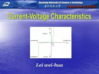
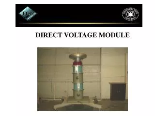
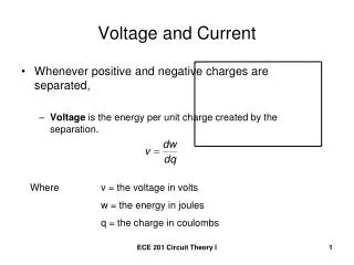
Direct Current Voltage Gradient. DCVG. With a Pipe Connection. Without a Pipe Connection. DCVG Surveys. DCVG Surveys. A DCVG survey is an electrical method of locating holidays in a pipeline coating. Hexcorder (DCVG) Half Cell Poles Cables Calibrated Half Cells Safety Equipment

E N D
With a Pipe Connection Without a Pipe Connection DCVG Surveys
DCVG Surveys • A DCVG survey is an electrical method of locating holidays in a pipeline coating.
Hexcorder (DCVG) Half Cell Poles Cables Calibrated Half Cells Safety Equipment Alignment Drawings Pipe Locator Radio Test leads GPS Current Interrupters Preparing to Undertake a Survey
Danger • Do not survey during a thunder storm or if thunder can be heard
DCVG Surveys • To easily locate coating defects you need pulsed DC current. This can be provided by the cathodic protection rectifiers using GPS Synchronized current interrupters. • If the pipeline is protected by sacrificial anodes then a temporary rectifier and interrupter needs to be installed. b
Installing A GPS Synchronized Interrupter • Sufficient current interrupters need to be installed such that all cathodic protection current is halted at the point of measurement during the instant OFF potential measurement
Starting the Hexcorder • Turn the Hexcorder ON by pressing the upper right yellow key, before suiting up with your equipment, to allow the GPS engine time to acquire the satellites.
Select Type of Survey • Select the survey type • C = Close Interval • D = Data Logger • V = CIPS+DCVG • G = DCVG • S = Side Drain
DCVG Surveys • Readings are usually taken 1 metre apart. • Always have both half cells on the ground when recording the voltage gradient.
Reference Electrode Calibration • If the potential difference between the half cells to be used during the survey and a new half cell is more than 5 mV then the half cells need service before use.
Put on Your Survey Equipment • Hexcorder • Half Cell extension poles • Connecting cables • Radio transceiver
Connect the Half Cell’s • Connect the half cells to the Hexcorder • Left to left connector, right to right connector • Tip Spray with DW-40 if the vegetation is wet
Half Cell Extension Pole • Connect the cables to the half cell extension poles and to the Hexcorder.
DCVG Without A Pipe Connection • DCVG • Used to locate coating defects and damage in pipeline coatings. • Does not indicate level of Cathodic Protection
Your Now Ready to Survey • The pipe locater should be just ahead of the surveyor to locate the pipe for the surveyor
Two Surveyors are Quicker than One • Purchase Cath-Tech Duel Surveyor Kit
Quick Menu • Pressing the white key labeled “MENU” allows comments to be quickly appended to your data. • You can enter your own comments Press 5 (Test) from the Main menu to edit the quick menu comments.
DCVG No Pipe Connection • The surveyor monitors the voltage gradient measured between two half cells over and beside the pipe. • When a voltage gradient is found the surveyor prospects for the location and size of the holiday
DCVG No Pipe Connection • Surveyor Walks over pipeline • IR drop creates voltage gradient in soil • Voltage gradient leads to epicenter • Soil contact important • One surveyor
Equipotential Lines at a Defect • Equipotential lines are established in the soil around a defect. • As the probe spacing increases the voltage gradient increases.
Defect Epicenter • Where the probe placemat crosses the equipotential lines a voltage gradient is measured. • When the probes are parallel to the equipotential lines a null is observed.
Equipotential Variations • Uniform equipotential lines are observed when a small defect is located on the top or bottom of the pipe. • Defects on the side give elliptical equipotential gradients
DCVG No Pipe Connection Advantages • No trailing wire • Less sensitive to AC and DC interference • Disadvantages • Laborious • Survey rate affected by terrain and coating condition
DCVG No Pipe Connection • Voltage gradients are measured in the soil around the pipe line
DCVG No Pipe Connection • The bar graph moving from the left to the right is a voltage gradient. • Current is flowing from left to right. • The scale of the bar graph is 0 - 150 mV.
DCVG No Pipe Connection • The bar graph moving from the right to the left is a voltage gradient. • Current is flowing from right to left. • The scale of the bar graph is 0 - 150 mV.
Bar Graph Scale • The bar graph has 3 ranges: • +/- 10.0 Millivolts • +/- 50.0 Millivolts • +/- 100.0 Millivolts • Press and hold 1 for 10 mV, press and hold 5 for 50 mV, press and hold 0 for 100 mV (confirmation left end of bar graph)
Gradient Display & Storage Modes • Press and hold “Q” display = O Alternating ON then OFF bar Graph • Press and hold “P” display = N Alternating (ON-OFF) then zero bar graph
Measures anodic and cathodic voltage gradients Indicates current flow direction Can record up to +/- 500 millivolts Voltage gradient, direction, GPS coordinates and time can be recorded in memory simultaneously. The Hexcorder DCVG or Millennium
DCVG No Pipe Connection • DCVG has been used worldwide with success for over 20 years • When used correctly, it is a good coating defect diagnostic tool • DCVG helps prioritize remedial actions
DCVG • The Hexcorder DCVG and Millennium models can measure and record the voltage gradient and the GPS coordinates of each measurement
Software • Special software is not required with the CATH-TECH™ HEXCORDER survey system. • Windows Hyper Terminal is used to down load the data. • Microsoft Excel or other spread sheet program is used to graph the data
Data Security • At the end of the day or more frequently the data should be down loaded to a PC and backed up on the hard drive and on diskette. • For added security editing of the survey data can not be accomplished after it is stored in the HEXCORDER's memory.
Data Format • The data can be exported in three formats: • ASCII comma delimited • Hexadecimal • ProActive
Downloading Data To A PC • Connect the Hexcorder to your PC with the supplied 9 Pin Serial cable.
The CATH-TECH™ Hexcorder Survey System • No special software is required to produce presentation quality graphs of your data gathered by the CATH-TECH™ Hexcorder Professional Survey Equipment
Thank you from the staff at: Cathodic Technology Limited 15-1 Marconi Court Bolton, Ontario Canada L7E 1E2 Ph. 905 857-1050 Fax 905 857-3499 Email ctl@corrosion-rust.com Web Site www.dcvg.net