Download
1 / 19
380 likes | 900 Views
Radiometric calibration. Coco Rulinda (CGIS-NUR) for PGD 2009 Based on slides by Boudewijn van Leeuwen , ITC-RSG-GTS. The Remote Sensing process. Image Data. Why Radiometric calibration?.

E N D
Radiometric calibration • Coco Rulinda (CGIS-NUR) for PGD 2009 • Based on slides by Boudewijn van Leeuwen, ITC-RSG-GTS Advanced Remote Sensing – PGD 2009
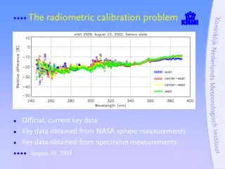
Why Radiometric calibration? • There are a number of important reasons to calibrate remote sensing data. The raw sensor DNs are simply numbers, without physical units. Each sensor has its own gain and offsets applied to the recorded signals to create the DNs. To do inter-sensor data comparison, they must be converted to at-sensor radiances. This step is called sensor calibration. If we desire to compare surface features over time, or to laboratory, or field reflectance data, corrections must be made for atmospheric, solar and topographic correction. We call this entire calibration and correction process radiometric calibration. Subject 1
Radiometric calibration process • Convert sensor’s DNs to at-sensor radiances requires sensor calibration information • Convert at-sensor’s radiances to radiance at earth surface difficult to achieve: view path atmospheric conditions at the time and locations of the image and sensor is required. • Correct from atmospheric, solar and topographic effects from surface radiance to surface reflectance
Radiance (L) • Energy measured by the sensor in Watt per square Meter per Steradian per Micron • (Wm-2sr-1μm-1) • or • Milliwat per square Centimeter per Steradian per Micron (mWcm-2sr-1μm-1)
DN to Radiance Conversion Lmin = minimum radiance (in Wm-2sr-1μm-1) Lmax=maximum radiance (in Wm-2sr-1μm-1) QCALmax=maximum DN value possible (=255) QCALmin=minimum DN value possible (=0 or 1)
Gain Settings • Scene specific • Usually described in the header file • To prevent saturation • Band 6 Low • Band 6 High When converting DNs to radiances always check the gain settings!
Radiance to Reflectance • Conversion of Radiance to Reflectance, why? • Reflectance (ρ) = wavelength dependent ratio between reflected and incoming energy • Unitless (0 – 1 or 0 - 100) • Normalization of Sun Angle • Normalization of irradiance
Reflectance (ρ) • Reflectance = ratio between reflected and incoming energy = Measured Energy Incoming Energy =LλЛd2 ESUNλcos θz Lλ= Radiance at sensor (in Wm-2sr-1μm-1) d2= Earth-Sun Distance (AU) θz = Solar Zenith Angle (deg) ESUN = Band dependent Exoatmospheric Irradiance (Wm-2μm-1) At-satellite reflectance ≠Surface reflectance
Earth – Sun Distance (d) - LUT • Distance Sun to Earth = ± 149 mln Km = 1 AU (Astronomical unit) J= Julian day Julian day: January 1st=001 Sin is in radian January 2nd=002
Exoterrestrial Solar Irradiance (ESUN)-LUT • Mean Irradiance for a specific bandwidth • Watt per square meter per micron (Wm-2μm-1)
Reflectance (ρ) - All • Lλ = Radiance at sensor (in Wm-2sr-1μm-1) • D2 = Earth-Sun Distance (AU) • ESUN = Band dependent Exoatmospheric Irradiance (Wm-2μm-1) • Θz = Solar Zenith Angle (deg)
Radiance to Temperature • Brightness Temperature; temperature of a blackbody (= perfect emitter) • At-satellite temperature ≠surface temperature
Sensor Calibration • Pre-flight calibration • Sensors degrade, so there is a need for: • In-flight calibration • Internal blackbody references; multiple calibrated lamps or panels • Solar calibrators • Hot and cold black body reference • Cross Calibration with space, airborne and ground measurements
More information • Landsat 7 Science Data Users handbook: http://ltpwww.gsfc.nasa/IAS/handbook/handbook_toc.html NOAA Solar Position Calculator http://www.srrb.noaa.gov/highlights/sunrise/azel.html