Download
1 / 26
260 likes | 286 Views
Signal Expressions. Multiply out: F = ((X + Y ¢ ) × Z) + (X ¢ × Y × Z ¢ ) = (X × Z) + (Y ¢ × Z) + (X ¢ × Y × Z ¢ ). New circuit, same function Sum of Products. Product of Sums Form. AND-OR NAND-NAND. Sum-of-products form. OR-AND NOR-NOR. Product-of-sums form.

E N D
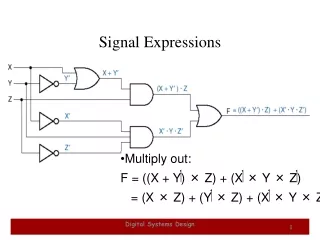
Signal Expressions • Multiply out:F = ((X + Y¢) × Z) + (X¢× Y × Z¢) = (X × Z) + (Y¢× Z) + (X¢× Y × Z¢) Digital Systems Design
New circuit, same functionSum of Products Digital Systems Design
Product of Sums Form Digital Systems Design
AND-OR NAND-NAND Sum-of-products form Digital Systems Design
OR-AND NOR-NOR Product-of-sums form Digital Systems Design
Shortcut: Symbol substitution Digital Systems Design
Different circuit, same function Digital Systems Design
Combinational-Circuit Analysis • Combinational circuits -- outputs depend only on current inputs (not on history). • Kinds of combinational analysis: • exhaustive (truth table) • algebraic (expressions) • simulation / test bench • Write functional description in HDL • Define test conditions / test vectors • Compare circuit output with functional description (or known-good realization) • Repeat for “random” test vectors Digital Systems Design
Combinational-Circuit Design • Sometimes you can write an equation or equations directly using “logic” (the kind in your brain). • Example (alarm circuit): • Corresponding circuit: Digital Systems Design
Alarm-circuit transformation • Sum-of-products form • Useful for programmable logic devices • “Multiply out”: Digital Systems Design
row N3 N2 N1 N0 F 0 0 0 0 0 0 1 0 0 0 1 1 2 0 0 1 0 1 3 0 0 1 1 1 4 0 1 0 0 0 5 0 1 0 1 1 6 0 1 1 0 0 7 0 1 1 1 1 8 1 0 0 0 0 9 1 0 0 1 0 10 1 0 1 0 0 11 1 0 1 1 1 12 1 1 0 0 0 13 1 1 0 1 1 14 1 1 1 0 0 15 1 1 1 1 0 Brute-force design • Truth table --> canonical sum (sum of minterms) • Example:prime-number & 1 detector • 4-bit input, N3N2N1N0 F = SN3N2N1N0(1,2,3,5,7,11,13) Digital Systems Design
Minterm list --> canonical sum Recall T10 Digital Systems Design
Algebraic simplification • Theorem T10 • Reduce number of gates and gate inputs Digital Systems Design
Resulting circuit Digital Systems Design
Circuit Optimization • Goal: To obtain the simplest implementation for a given function • Optimization is a more formal approach to simplification that is performed using a specific procedure or algorithm • Optimization requires a cost criterion to measure the simplicity of a circuit • Two distinct cost criteria we will use: • Literal cost (L) • Gate input cost (G) and cost with NOTs (GN) Systems Design
Literal Cost • Literal – a variable or it complement • Literal cost – the number of literal appearances in a Boolean expression corresponding to the logic circuit diagram • Examples: • F = BD + AB’C + AC’D’ L = 8 • F = BD + AB’C + AB’D’ + ABC’ L = • F = (A + B)(A + D)(B + C +D’)(B’ + C’ + D) L = • Which solution is best? 11 10 Digital Systems Design
Gate Input Cost • Gate input costs - the number of inputs to the gates in the implementation corresponding exactly to the given equation or equations.(G - inverters not counted, GN - inverters counted) • For SOP and POS equations, it can be found from the equation(s) by finding the sum of: • all literal appearances • the number of terms excluding terms consisting only of a single literal,(G) and • optionally, the number of distinct complemented single literals (GN). • Example: • F = BD + AB’C + AC’D’G = 11, GN = 14 • F = BD + AB’C + AB’D’ + ABC’G = , GN = • F = (A + B)(A + D)(B + C +D’)(B’ + C’ + D) G = , GN = • Which solution is best? 15 19 17 14 Digital Systems Design
GN = G + 2 = 9 L = 5 G =L+ 2 = 7 B C A F • L (literal count) counts the AND inputs and the single literal OR input. • G (gate input count) adds the remaining OR gate inputs • GN(gate input count with NOTs) adds the inverter inputs Cost Criteria (continued) • Example 1: • F = A + B C + B’C’ Digital Systems Design
A B C F A B C F Cost Criteria (continued) • Example 2: • F = A B C + A’B’C’ • L = 6 G = 8 GN = 11 • F = (A + C’ )( B’ + C)( A’ + B) • L = 6 G = 9 GN = 12 • Same function and sameliteral cost • But first circuit has bettergate input count and bettergate input count with NOTs • Select it! Digital Systems Design
Boolean Function Optimization • Minimizing the gate input (or literal) cost of a (a set of) Boolean equation(s) reduces circuit cost. • We choose gate input cost. • Boolean Algebra and graphical techniques are tools to minimize cost criteria values. • Some important questions: • When do we stop trying to reduce the cost? • Do we know when we have a minimum cost? • Treat optimum or near-optimum cost functionsfor two-level (SOP and POS) circuits first. • Introduce a graphical technique using Karnaugh maps (K-maps, for short) Digital Systems Design
Karnaugh Maps (K-map) • A K-map is a collection of squares • Each square represents a minterm • The collection of squares is a graphical representation of a Boolean function • Adjacent squares differ in the value of one variable • Alternative algebraic expressions for the same function are derived by recognizing patterns of squares • The K-map can be viewed as • A reorganized version of the truth table • A topologically-warped Venn diagram as used to visualize sets in algebra of sets Digital Systems Design
Some Uses of K-Maps • Provide a means for: • Finding optimum or near optimum • SOP and POS standard forms, and • two-level AND/OR and OR/AND circuit implementations for functions with small numbers of variables • Visualizing concepts related to manipulating Boolean expressions, and • Demonstrating concepts used by computer-aided design programs to simplify large circuits Digital Systems Design
y = 1 y = 0 m m 0 = 1 = x = 0 x y x y m 2 = m 3 = x = 1 x y x y Two Variable Maps • A 2-variable Karnaugh Map: • Note that minterm m0 and minterm m1 are “adjacent” and differ in the value of the variable y • Similarly, minterm m0 and minterm m2 differ in the x variable. • Also, m1 and m3 differ in the x variable as well. • Finally, m2 and m3 differ in the value of the variable y Digital Systems Design
Input Function y = 0 y = 1 Values Value (x,y) F(x,y) x = 0 a b 0 0 a d c x = 1 0 1 b 1 0 c 1 1 d K-Map and Truth Tables • The K-Map is just a different form of the truth table. • Example – Two variable function: • We choose a,b,c and d from the set {0,1} to implement a particular function, F(x,y). Function Table K-Map Digital Systems Design
y = 1 y = 0 F = x 0 0 x = 0 x = 1 1 1 = + = F ( x , y ) x y x y x K-Map Function Representation • Example: F(x,y) = x • For function F(x,y), the two adjacent cells containing 1’s can be combined using the Minimization Theorem: Digital Systems Design
y = 1 G = x+y y = 0 x = 0 0 1 x = 1 1 1 = + + + = + G ( x , y ) x y x y xy x y x y K-Map Function Representation • Example:G(x,y) = x + y • For G(x,y), two pairs of adjacent cells containing 1’s can be combined using the Minimization Theorem: ( ) ( ) Duplicate xy Digital Systems Design