Download
1 / 16
170 likes | 284 Views
Explore the active region assumptions and excess carrier concentrations in a Bipolar Junction Transistor (BJT) analysis, focusing on the emitter, base, and collector regions. Understand the calculations and distribution of minority carriers within the transistor.

E N D
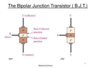
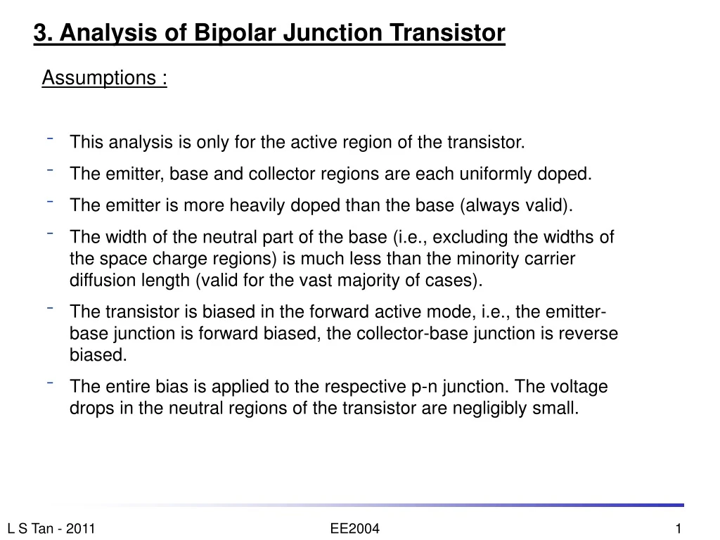
3. Analysis of Bipolar Junction Transistor • Assumptions : • This analysis is only for the active region of the transistor. • The emitter, base and collector regions are each uniformly doped. • The emitter is more heavily doped than the base (always valid). • The width of the neutral part of the base (i.e., excluding the widths of the space charge regions) is much less than the minority carrier diffusion length (valid for the vast majority of cases). • The transistor is biased in the forward active mode, i.e., the emitter-base junction is forward biased, the collector-base junction is reverse biased. • The entire bias is applied to the respective p-n junction. The voltage drops in the neutral regions of the transistor are negligibly small.
IEn ICn 3.1 BJT current components Base(p) Emitter(n) Collector(n) IEp ICp IBa IBb + VBC - IC IE - VBE + IB IEn is the emitter current component due to injection of electrons from the emitter to the base. IEp is the emitter current component due to injection of holes from the base to the emitter. IBais the hole current from the base which feedsIEp. IBbis the hole current from the base which supplies the holes for recombination in the base. ICn is the collector current component due to the part of the injected emitter electrons (IEn)which do no recombine in the base and manage to reach the collector. ICp is the hole component of the leakage current due to the reverse biased collector base junction; it is usually negligibly small compared to ICn.
x x E B p n + n Collector Base Emitter n o BASE i EMITTER n COLLECTOR t a o i r t t a n r e t n c e n c o n C o r C e i r r r e i a r r C a s C s e s s c x e c E x E x -nB0 -pC0 3.2 Excess Minority Carrier Concentrations in the BJT • Short base, • xB<< Ln. • Assume short emitter, xE<< Lp, in this example, though it is also possible for emitter to be “long”. • The collector is assumed long. This is, however, immaterial to the operation discussed here. δpE(x) δnB(x)
x B + n Colle p Base n Emitter ctor Rev Bias – Carrier Extraction Fwd Bias – Carrier Injection COL n o n i t o BASE a i LEC t r EMITTER a t r n t e n TOR c e n c o n δnB(0)=nB0[exp (eVBE/kT)-1] C o r C e i r δpE(0) =pE0[exp (eVBE/kT)-1] r e r i a r r C a C s δpC(0) = - pC0 s s e s c e x c E x E δnB(xB)= - nB0 δpE(xE)=0 x xE xB Excess minority carrier concentrations at SCR edges of an npn BJT in forward active mode.
Excess minority carrier concentration Ohmic metal contact Base Emitter x” = 0 x” = xE Boundary conditions of excess minority carriers at the edges of the space charge regions (SCRs) : Emitter : Edge of E-B SCR : From the theory of a forward-biased p-n junction, Emitter contact : At the ohmic contact, there are no excess carriers as they have all recombined at the contact. δpE(0) δpE(xE) x”
Excess minority carrier concentration Collector Emitter Base x = 0 x = xB Base : Edge of E-B SCR : From the theory of a forward-biased p-n junction, edge of C-B SCR : From the theory of a reverse-biased p-n junction, δnB(0) δnB(xB) Note : The total electron (minority carrier) concentration at the edge of the C-B SCR is zero due to the reverse bias of that junction(see theory of p-n junction). The excess carrier concentration is therefore negative. x
Excess minority carrier concentration Base Collector x’ = xC x’ = 0 Collector : Edge of B-C SCR : From the theory of a reverse-biased p-n junction, Collector ohmic contact : Ohmic metal contact δpC(xC) δpC(0) x’
Excess minority carrier concentration δnB(x) Collector Emitter Base x = 0 x = xB • In the neutral region of the base : • The excess minority carriers (electrons in this case) injected from the emitter into the base diffuse through the neutral region of the base towards the collector. • Since the width of the neutral base, xB, is much less than the minority carrier (electron) diffusion length, Ln, practically no excess minority carriers recombine within the neutral base. • The minority carrier (electron) diffusion current through the neutral base is constant. • The distribution of the excess minority carriers in the base is practically a straight line.
Excess minority carrier concentration δnB(x) nB0[exp (eVBE/kT)-1] approximate IEn actual x -nB0 Collector Emitter Base x = 0 x = xB • Calculation of IEn • In a real bjt, since there is some recombination, the minority carrier (electron) distribution in the base is a slightly exponential curve. • However, since the amount of recombination in the base is very small, because xB << Ln, the curve is very nearly like a straight line. • For our analysis, we shall use the straight line approximation. • IEn is due to the diffusion of the electron through the base, therefore Note: Ais the cross-sectional area of the BJT. The negative sign of IEn indicates that it is in the – x direction.
Excess minority carrier concentration δpE(x) pE0[exp(eVBE/kT-1] IEp Emitter Base x’’ = xE x’’ = 0 • Calculation of IEp • In this example, we assume a short emitter, i.e., xE << Lp. • The minority carrier (hole) distribution in the emitter is then also a straight line. • IEp is due to the diffusion of the holes through the neutral part of the emitter. because in forward active operation. Note : 1. IEp as expressed above is in the + x” direction, which is opposite to the + x direction. 2. If the emitter is long, xE >> Lp, then xE in the above expressions should be replaced by Lp. x x”
Excess minority carrier concentration δnB(x) nb0[exp (eVBE/kT)-1] IEp -nB0 Collector Emitter Base x = 0 x = xB IBb IBa • Calculation of IBa and IBb • The base current consists holes and is made up of two components. • IBa is the component that supplies holes for injection into the emitter. Therefore, • IBa = IEp • IBb is the component that supplies holes for recombination with the excess electrons in the base. • Base recombination current • = excess base minority charge • minority carrier lifetime • = • where Ais the cross-sectional area of the BJT. δnB(x)
Excess minority carrier concentration δnB(x) nb0[exp (eVBE/kT)-1] iEp -nB0 Collector Emitter Base x = 0 x = xB iBb iBa • The integral represents the • area under the curve of δnB(x) in the base. • Since xB << Ln, the recombination in the base is very small, and the excess minority carrier distribution (dashed line), δnB(x), can be approximated by a straight line (solid line). • Also, we can make the approximation δnB(xB) = 0. • The integral is then given by the area under the straight line approximation of δnB(x), i.e., δnB(x) because in forward active operation.
IEn ICn Calculation of ICn Base(p) Emitter(n) Collector(n) IEp ICp IBa IBb + VBC - IC IE - VBE + IB • ICp, the hole leakage current that flows through the reverse-biased collector-base junction, is very small and can be neglected under forward active condition. • ICn, is made up of the flow of those electrons that diffuse across the base and did not recombine with holes within the base. Therefore,
Collector current, because the leakage current ICp is very small. because the recombination current IBb << IEn. Therefore, where The collector current, IC , that flows through the collector-base junction is controlled by the voltage across the emitter-base junction, VBE. ----- TRANSISTOR ACTION Note that we equate the magnitudes of IC, ICn and IEn without considering the sign because they are all defined in the same (- x ) direction. See previous slide.
Example 1 Objective: To calculate the collector current given the minority carrier injection in the base. Consider an npn transistor with a uniform cross-sectional area of 0.1 mm2 which has an excess electron concentration of 8.5 x 1015 cm-3 maintained at the emitter-base junction. The collector-base junction is reverse biased. If the width of the neutral base region is 5 μm and the electron mobility is 1500 cm2 V-1s-1, estimate the collector current. The doping in the base, NAB = 2.25 x 1017 cm-3. The minority carrier lifetime in the base, τn = 0.1 X 10⁻⁶ s. The intrinsic carrier concentration, ni = 1.5 x 1010 cm-3.
δnB(x) Excess minority carrier concentration 8.5 x1015 cm-3 approximate iEn iC actual x -nB0 Collector Emitter Base x = 0 x = xB Solution to Example 1