Download
1 / 31
360 likes | 632 Views
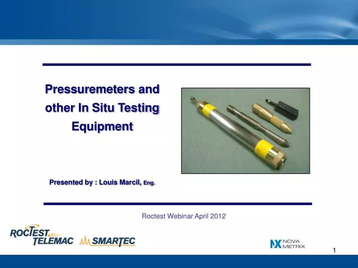
Pressuremeters and other In Situ Testing Equipment Presented by : Louis Marcil, Eng. Roctest Webinar April 2012. Presentation Overview. INTRODUCTION 1. Pressuremeters (PMT) 1.1 Description of the Test 1.2 Description of the Equipment (Types of Pressuremeters )

E N D
Pressuremeters and other In Situ Testing Equipment Presented by : Louis Marcil, Eng. Roctest Webinar April 2012
Presentation Overview INTRODUCTION 1. Pressuremeters (PMT)1.1 Description of the Test 1.2 Description of the Equipment (Types of Pressuremeters) 1.3 Main Applications 1.4 Advantages and Limitations 2. Other In Situ Test Equipment 2.1 Vane Testers 2.1 Cone Penetration Test Equipment (CPT) CONCLUSION
INTRODUCTION IN SITU TESTING Proper characterization of mechanical properties of the ground onto which structures are to be built has a great importance. Pyramid Initial Slope Rhomboidal ‘bent’ Pyramid, Egypt
INTRODUCTION • IN SITU TESTING • Means for characterizing the ground: • Laboratory Testing • In Situ Testing • - Penetration Resistance Measurement (SPT, CPT) • - In Situ Permeability Tests (Packer Test, Rising Head Test...) • - Strength and compressibility testing (PMT, Vane Testing, Plate load tests, Flat Dilatometer…)
1 Pressuremeters PMT = An in situ loading test executed by radial expansion of a cylindrical cavity. The stresses are exerted on the walls of a borehole by mean of a pressurized fluid acting on one inflatable membrane.
1.1 Test Description TYPICAL PRESSUREMETER CURVE • Progressive loading in steps. Waiting period required at every step for stabilization before recording pressure and radial expansion • Unload-loading cycle • Test duration : 10 min • Standards: ASTM 4719-07 NF P94-110-1, EN_ISO_22476-4
1.1 Test Description • General Testing Procedure • Tests executed at various depths in the same borehole • Common spacings : 1 to 3 m. • Borehole cannot be done in one pass • Results are presented for each elevation giving general profile of the soil.
1.1 Test Description Main Parameters: • Limit pressure (Pl) • Pressuremeter modulus (E) • . Where: - R : Poisson's ratio of the soil/rock - Vm : the volume of the cavity at mid-point of the testing zone - : the variation of volume of the cavity due to the variation of the applied pressure
1.1 Test Description The Making of the Borehole = Critical to make successful tests ! ! ! Borehole = Adequate if: 1. Undisturbed Soil 2. Borehole of Proper Diameter 3. Smooth wall borehole
1.1 Test Description Various drilling methods suggested in Standards as per type of soils. • Use of rotary drilling with axial injection (towards hole bottom) of mud is applicable in most cases. Slotted casing in large-gravels soils. • Ideally: Roller bit for silt, sand, and gravel. 2 7/8 in. to 3 inches. Three-wing bit for clayey soils. • Diameter of rods must be one or two sizes smaller than diameter of bit to allow good flow up of cuttings • Do not ram the bit up and down as this will result in an oversized hole • Popular method : 3-in hollow auger for first portion of the borehole + use of rotary bit in the testing zone only • Go slowly: • Injection pressure: < 500 kPa with borehole full of mud • Bit rotation: < 60 rpm • Flow : < 15 liters per minute • Bit pressure: < 200 kPa (100 kg in a 76 mm borehole) • Typical advance rate: 15 to 25 cm/minute
1.2 The Equipment • VARIOUS TYPES OF PRESSUREMETERS: • Pre-Boring vs Self-Boring Pressuremeters • Volume Variations vs Direct Radial Strain Measurements • Mono-cellular vs Tri-cellular Probes • Diameter of the Probe : 33 mm to 95 mm • Type of Loading: Pneumatic vs Hydraulic • Reading Mode: Manually vs Automatically • Working Capacity: 4,000 kPa to 30,000 kPa • Various Sensitivities
1.2 The Equipment Soil Pressuremeters: TexamPressuremeter (Volumetric, hydraulic, mono-cellular probe Menard Pressuremeter (Volumetric, pneumatic, tri-cellular probe) TrimodsPressuremeter (Radial expansion measurement, hydraulic, mono-cellular probe)
1.2 The Equipment Rock Pressuremeters: • Model PROBEX • Capacity pressure: 30 000 kPa (3500 psi) • Hydraulically loaded • Fiberglass-reinforced polyurethane membrane • Capacity modulus: 0.01 to 30 GPa approx. • Testing depth to (date): 300 meters
1.2 The Equipment Rock Pressuremeter / Borehole Dilatometer: • Model DMP • Measures radial deformations by mean of 3 LVDT disposed at 120 ° • Capacity pressure: 20 000 kPa • For used in soft to moderately hard rock (Maximum modulus of 50 GPa)
1.2 The Equipment Self-Boring Pressuremeters: • Interesting tool because minimizes remolding • Confined to soils with few gravels BOREMAC Pressuremeter (volumetric, hydraulic, mono-cellular probe)
1.3 Main Applications • Shallow foundations • Laterally loaded piles • Vertically loaded piles • Compaction control • Design of pavement • Of less use for slope stability problems and embankments
1.3 Main Applications Semi-empirical methods vs. methods based on the theory of elasticity Semi-empirical method: 1) Bearing Capacity = K x Pl The factor of proportionality K is function to: - Relative depth - Shape of the foundation - Type of ground
1.3 Main Applications 2) Settlement : Ref: Canadian Foundation EngineeringManual - S is the settlement - EM is the pressuremeter modulus. - qa is the allowable bearing capacity - λ2 and λ3 are the coefficients of shape of footing, (L/B) - B is the width of the footing - αp is a coefficient of structure (function to type of soils and E/Pl)
1.3 Main Applications 3) Lateral Deflection of laterally-loaded structures P-Y Curve: Various Methods Robertson et al. Example : VGS Reduction of Rock Pressuremeter Tests Design P-Y Curves 54-inch Diameter Rock Socket (Courtesy: Failmezger, In Situ Soil Testing, VA)
1.3 Main Applications Design of High Rise Buildings AT&T Tower (Chicago, USA) Petronas Towers (Kuala Lumpur, Malaysia)
1.4 Advantages and Limitations • LIMITATIONS • Well-trained operator is required for ensuring: • Making a good borehole • Taking care not to burst too many membranes • Soils with large gravels are difficult to test. A slotted casing might be required.
1.4 Advantages and Limitations • ADVANTAGES • Versatile: Can be performed in most types of soils and soft rocks • Gives an in situ stress strain curve • The loading sequence can be adapted according to the application (long or rapid loading, cyclic loading) • Close analogy with laterally-loaded piles • Validity of the test can be controlled from the shape of the curve.
2. Other In Situ Testing Equipment • Various types of in situ tests can be performed: • Penetration Test (SPT, CPT), Vane Test, Plate Loading Test, Flat Dilatometer Test, Packer Test, Compaction Control Test, etc.
2.1 Vane Shear Tester • For cohesive soils only • Test Description • Quick and Easy • Used either for designing of shallow or deep foundations
2.1 Vane Shear Tester • Su = K (as - af) x C • Where: • Su = the undrained shear strength in kg/cm2 • C = vane form constant in 10-2 x cm-3 • K = calibration constant for the torque recording head in kg m / cm • as = distance in cm between the zero torque reference line to the peak of the curve • af = distance in cm between the zero torque reference line and the circular arc scribed during the first 15 degrees of rotation (corresponds to rod friction) Recording sheets from the Model M-1000 Vane Tester
2.2 Cone Penetration Test • Dynamic Cone Penetration Test: • Procedure: Record number of blow counts required for trusting a conical point into the ground. Size and shape of the point, weight, and the mass falling distance are standardized. • Used for soil classification and for compaction control. Model PEM-1 Cone Dynamic Penetrometer
2.2 Cone Penetration Test • Static Cone Penetration Test (CPT) : • The most common penetration test. • Pushed into the ground. • Recording of: tip resistance, friction resistance, pore pressure and others. • Models: • Handsounding Cone Penetrometer (1) • Mechanical Cone (2) • Mechanical Friction Cone (3) • Electric Cones (4) 2 1 4 3
2.2 Cone Penetration Test Static Cone Penetration Test (CPT) : Interpretation and use of results: Soil Classifications using cone and friction resistance. Determination of various parameters from empirical correlations: For instance: - Stiffness and relative density in cohesionless soils. - Undrained Shear Strength in cohesive soils.
CONCLUSION Roctest has specialized in pressuremeters PMT not a routine testing method Required well-trained operator Special attention must be given for the making of the borehole PMTprovesto be a useful tool for applications : 1) Such as for the laterally loaded foundations, and high rise buildings 2) Where undisturbed samples cannot be obtained, and where other conventional tests cannot be done (rock & weakly cemented material) 3) On large projects where it is justified to put efforts to get better information on the soil/rock
Thankyou ! Questions ? (Courtesy of ODOT)