Download
1 / 36
440 likes | 882 Views
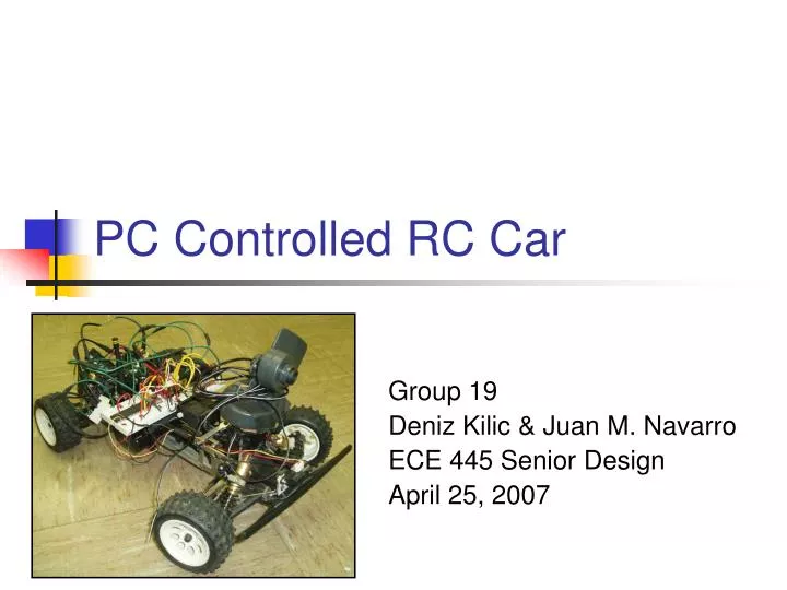
PC Controlled RC Car. Group 19 Deniz Kilic & Juan M. Navarro ECE 445 Senior Design April 25, 2007. Introduction. Build PC Controlled RC Car Blends Wireless Communications Remote Sensing Mechanisms Security Applications Develop Serial Port Interface Control RF transmitters from PC

E N D
PC Controlled RC Car Group 19 Deniz Kilic & Juan M. Navarro ECE 445 Senior Design April 25, 2007
Introduction • Build PC Controlled RC Car • Blends Wireless Communications • Remote Sensing Mechanisms • Security Applications • Develop Serial Port Interface • Control RF transmitters from PC • Send signals to RC car
Benefits • Allows users to monitor their home remotely • Serves as security vigilante for various applications • Virtual watch-dog • Appealing toy for all ages!
Features • Radio Controlled • On-board Wireless Camera • Proximity Sensor • Precision Steering • Remote Login Capability • Camera Turret
Hardware X10 Wireless Camera • 12V DC input • Frequency of 2.4 Hz • Transmits signal to receiver connected to PC
Hardware Sabrent Tuner Video Capture Box • Converts video signals • USB connection directs video signal to a PC • Input from the X10 Wireless Camera Receiver • Video signals will be fed into GUI that will allow the user to see what X10 Wireless Camera records
Hardware • Hardware Interface to the local PC • USB connection to capture the video signals arriving at the X10 Wireless Camera Receiver • Serial Interface connection sends information to the transmitter Computer Output Panel
Hardware Linx Transmitter • TXM-900-HP3-PPS • Receives data from the serial port of the PC
Software Overview Graphical User Interface on Host PC • Video Capture • Mouse Controller
Software Design Mouse Controller • Main control mechanism • Moving the mouse cursor around the Cartesian plane results in a vector whose starting point is the center and whose tip will be the mouse pointer • Magnitude proportional to the speed of the vehicle • Angle proportional to the direction on the RC Car steering
Transmitter Software • Interrupt-driven • Multi-threaded program • Processes mouse motions/left and right key presses • Left or right mouse keys control the direction the camera turret servo will spin • Exit when the user presses ESC or closes the program down
Hardware • RXM-900-HP3-PPS • Receives asynchronous data from RF Transmitter • Sends data to microprocessor Linx Receiver
Hardware Servo Motors • 2 servo motors • Allows camera turret to rotate 360 degrees • Controls the steering mechanism in the RC Car frame
Hardware DC-to-DC Converter • Input ranges from 8V DC to 32V DC • Output of 24V DC • Rated Output Current of 130 mA • Output Power of 3 Watts • Steps up the voltage from 7.2V DC
Hardware Relays • Separates the low voltage/current TTL logic signals of the PIC from the higher voltage/current signals of the motor • Powers drive train motor • Controls the direction of drive train motor spins
Hardware • Voltage Regulator • Provides Steady 5V DC Output • Rated for 1.2 A Maximum • Current Amplifier • Reduces Strain on PIC • Draws Less Current from PIC
Hardware Microprocessor • Main control center for our RC Car • Reads incoming signals • Outputs control signals • Processes closed-loop feedback signals without user interaction
Hardware Fuses • 4A fuse protects our RC Car motor circuit • 300 mA fuses protect our TTL logic lines Crystal Oscillator • Provides a square wave clock signal • Frequency of 20 MHz • Maximum input current of 17 mA
Hardware MAX 232 Chip • Dual driver/receiver • Single power supply • Connects to the microcontroller to generate proper voltages • RS232 & TTL converter
Hardware IR Proximity Sensor • Provides an analog output voltage proportional to the distance of the object it senses • Detecting range is between 4 cm and 30 cm • Output voltage between 0V and 3.2V DC • Input Rating: 7V DC at 50 mA of current
Receiver Software • Executed procedurally • Checks the proximity sensor • Controls the direction of RC Car • Controls camera turret in a certain direction • Exit when the system is shut down or runs out of power
IR Sensor Control Logic • 60 is approximately 12 cm which is 1.1 V. if(value < 60) { if(input(PIN_B1) == 1) { printf("Main Power Relay is ON. Value = %d\n“, value); delay_ms(2000); } output_high(PIN_C1); // main on/off relay, pin #16 } else { if(input(PIN_B1) == 1) { printf("Main Power Relay is OFF.\n"); delay_ms(2000); } output_low(PIN_C1); // main on/off relay, pin #16 }
Transmitter/Receiver Test Duty Cycle: 25% Frequency: 100 Hz Period: 0.01 sec
PWM Output Test Duty Cycle: 12.2% Frequency: 1220 Hz Period: 819.67 usec
Successes • Communication from PIC to PC • Proximity Sensor • Steering Controls • Camera Turret • Linx Transmitter/Receiver Communication • Control Relays
Challenges • Communication from PC to PIC • Servo Torque • Sound Sensor Sensitivity • PWM Control from PIC • Integrated Graphical User Interface • DC-to-DC Converter
Recommendations • Higher Torque Servos • Sensitive Sound Sensors • Avoid Mechanical Relays for PWM • Use Interrupts for PWM
Special Thanks… Professor Swenson Hyesun Park Alex Spektor Jon Weber ECE Parts Shop ECE Department