Download
1 / 25
320 likes | 560 Views
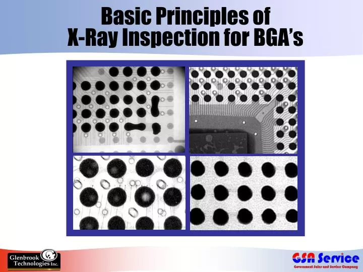
Basic Principles of X-Ray Inspection for BGA’s. Increased Use of BGA’s. Ball Grid Arrays - array of solder ball connections underneath component Provides many advantages over leaded components Reduced component size Increased I/O count Smaller footprint

E N D
Increased Use of BGA’s • Ball Grid Arrays - array of solder ball connections underneath component • Provides many advantages over leaded components • Reduced component size • Increased I/O count • Smaller footprint • Increased performance characteristics
The Problem with BGA’s • How to verify a solder bond that cannot be observed? • Hidden joints - touch up not possible • Only way to test integrity of joints • Electrical test • Look Under/Video Scope • X-Ray
Presence or Absence of Material wedge object x-rays x-rays detector image Differences in Material Density high density material x-rays low density x-rays detector image How X-Rays Work
X-ray tube generates x-ray energy The image you see X-rays absorbed where density exists in sample - remaining x-rays pass through & strike the detector Detector converts x-rays to visible light, video camera sends image to processor Image Processor enhances x-ray images for high-resolution viewing How an X-Ray System Works
Solder Connections Under X-Ray Analysis • Main characteristic: uniformity of the connections • If X-ray shows all connections uniformly circular & equal in area - good indication of complete/proper reflow
Nearly all Defects have “Signatures” • Bridging, missing balls, large voids obvious • Other defects subtle • Look for pattern in distortion of size/shape of bond image • Operator learns to identify defect signatures, process problems and quickly make adjustments
Look Under Scope Image Defects Identified by X-Ray: Bridging • May be due to excess paste or flux • Improper rework implicated • Solder splattering due to poor reflow conditions
Misregistration • Result of errors in component placement • Possible issues with solder mask alignment
Insufficient Reflow • More difficult to spot • If package misplaced, ball shape may be elliptical (easier to identify) • Bond distribution not consistent
Missing Balls • Can occur in manufacturing process • Usually due to mishandling
Cold Solder • More difficult to identify • Signified by jagged irregular edge around the perimeter of the solder ball
Solder Voids • Result of moisture in BGA package – must be thoroughly baked out • Problems with solder paste • Huge issue with lead-free solder
Solder Voids • Voids a process indicator, not defect unless excessively large • Motorola Study - balls that contain voids up to 24% more reliable than those without voids!
At 50 kV At 70 kV Solder Voids & Voltage Blooming • Associated with camera used in many X-ray systems • As voltage increased, void artificially appears to expand (bloom) • Makes void appear larger than it really is • Glenbrook systems not subject to voltage blooming
Normal Potato Chipping Potato Chipping/Popcorning • BGA’s outside edge lifts up from a pad • Center joints squashed due to compression under die area • Caused by moisture in BGA or excessive topside temperature
Potato Chipping/Popcorning • Note distortion/ warpage of ball bonds lower right corner • View through Look-Under scope. Note package peeling away from solder ball
Opens (require angled viewing) • Ball smaller than adjacent balls • Pad shadow seen below indicating no contact between ball & pad • Note two unattached spherical shapes unlike oval shapes adjacent to it • indicate no contact between pad & solder ball
RTX-113HV X-Ray Inspection System • Features powerful 80 kV X-ray tube • GTI-5000 image processor with auto-BGA analysis software • Sees through dense multilayer PCBs & metal capped BGAs • Variable Angle Viewing allows for 45 degree viewing
GTI-5000 Image Processing Software • Provides analysis of BGA defects: bridging, voids, missing balls • Measures BGA ball size, ball roundness & void size • Software identifies any ball outside of set tolerance • Includes CPU, Frame Grabber, Software, Color Monitor
Variable Angled Viewing • Allows for 45 degree viewing • X-Ray source is rotated • Allows inspection for full range of hidden BGA defects: • Missing or mis-registered solder spheres • Misalignments • Gross solder voids • Non-wetting or non-contact
Specifications: RTX-113HV • Operating voltage: 120V, 50/60 Hz • Energy sensitivity: < than 15kV to >160 kV • X-Ray Tube – 80 kVA • Resolution: >20 line pairs per millimeter; can easily resolve a 1 mil bond wire • Magnification: 4 - 50x • Maximum field of view: 1” diameter circle • Maximum PCB size: 27” x 27” (685mm x 685mm) with PCB manipulator
RTX-113 RTX-Mini JewelBox Series • 35-52kV • 20 line pairs/mm resolution (up to 100 optional) • Variable Angle Viewing option available • 40kV • 20 line pairs/mm resolution • Truly Portable – can be hand carried or shipped! • 80 or 90kV • 5-7, or 10 micron Focal Spot size • 7x-2000x magnification • 5 Axis, 360o Positioner Other Real-Time X-Ray Inspection Systems from Glenbrook Technologies
Manufacturer’s RepAaron Caplan1310 E. Maple AveSterling, VA 20164(703) 731-8048aaron@gsaservice.com www.gsaservice.com 11 Emery AveRandolph, NJ 07869Tele: (973) 361-8866Fax: (973) 361-9286szweig@glenbrooktech.com www.glenbrooktech.com
Manufacturer’s RepAaron Caplan1310 E. Maple AveSterling, VA 20164(703) 731-8048aaron@gsaservice.com www.gsaservice.com 11 Emery AveRandolph, NJ 07869Tele: (973) 361-8866Fax: (973) 361-9286szweig@glenbrooktech.com www.glenbrooktech.com