1 / 36

Figure 10.1 Flow in a duct with area change.

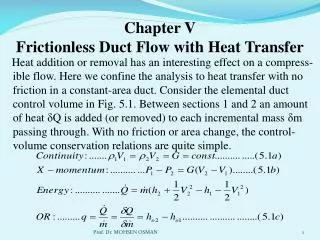
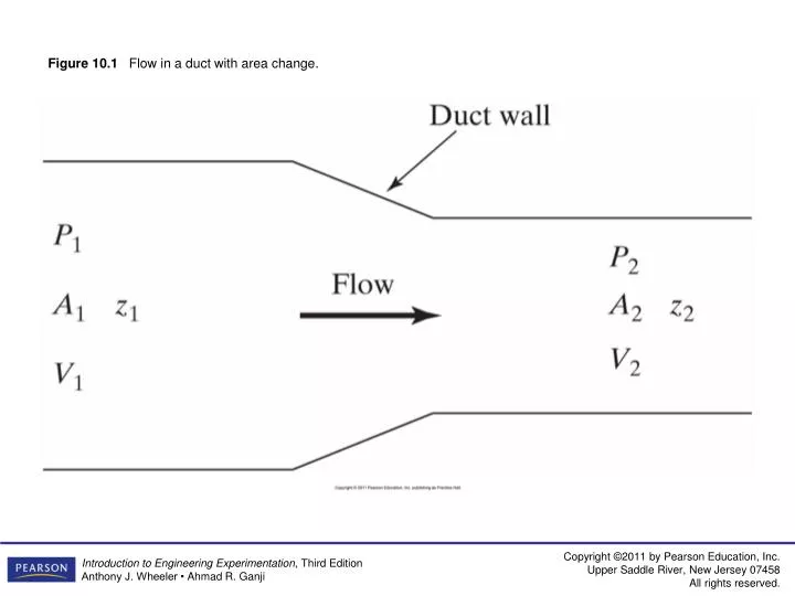
Figure 10.1 Flow in a duct with area change. Figure 10.2 Flowmeter using venturi tube. Figure 10.3 Dimensional specifications of venturi tube. (Based on ASME, 1989.). Figure 10.4 Flow nozzle.

taya
Download Presentation

Figure 10.1 Flow in a duct with area change.

An Image/Link below is provided (as is) to download presentation Download Policy: Content on the Website is provided to you AS IS for your information and personal use and may not be sold / licensed / shared on other websites without getting consent from its author. Content is provided to you AS IS for your information and personal use only. Download presentation by click this link. While downloading, if for some reason you are not able to download a presentation, the publisher may have deleted the file from their server. During download, if you can't get a presentation, the file might be deleted by the publisher.

E N D

Presentation Transcript


  1. Figure 10.1 Flow in a duct with area change.

  2. Figure 10.2 Flowmeter using venturi tube.

  3. Figure 10.3 Dimensional specifications of venturi tube. (Based on ASME, 1989.)

  4. Figure 10.4 Flow nozzle.

  5. Figure 10.5 Dimensional specifications for ASME long-radius flow nozzles. (Based on ASME, 1989.)

  6. Figure 10.6 (a) Orifice meter system; (b) description of square-edged orifice.

  7. Figure 10.7 Location of orifice meter pressure taps: (a) flange taps; (b) D-1/2D taps; (c) corner taps.

  8. Figure 10.8 Laminar flowmeter.

  9. Figure 10.9 Sketch of rotameter.

  10. Figure 10.10 Turbine flowmeter.

  11. Figure 10.11 Paddle-wheel flowmeter.

  12. Figure 10.12 Thermal mass flowmeter.

  13. Figure 10.13 Coriolis mass flowmeter: (a) schematic of single tube; (b) practical implementation.

  14. Figure 10.14 A positive-displacement flowmeter.

  15. Figure 10.15 Vortex shedding flowmeter.

  16. Figure 10.16 Transit-time ultrasonic flowmeter.

  17. Figure 10.17 Velocity profile in a duct.

  18. Figure 10.18 Hot-wire air mass flowmeter.

  19. Figure 10.19 Volumetric gas measurement.

  20. Figure 10.20 Pitot-static velocity probe.

  21. Figure 10.21 Hot-wire probe.

  22. Figure 10.22 Constant-temperature hot-wire anemometer system.

  23. Figure 10.23 Constant-current hot-wire anemometer circuit.

  24. Figure 10.24 Dual-beam laser velocimeter.

  25. Figure 10.25 Fringes in sensing volume.

  26. Figure 10.26 Float-type level systems.

  27. Figure 10.27 Differential pressure level-measuring system.

  28. Figure 10.28 Capacitance level-measuring system.

  29. Figure 10.29 Ultrasonic fluid level system.

  30. Figure 10.30 Tank weighing method for fluid level.

  31. Figure 10.31 Schematic diagram of a typical NDIR gas analysis system. (Based on Wark and Warner, 1981.)

  32. Figure 10.32 Schematic of a chemiluminescent measurement device. (Based on Lodge, 1989.)

  33. Figure 10.33 Schematic flow diagram of a chemiluminescent NOx analyzer.

  34. Figure 10.34 Schematic of flame ionization detector. (Based on Wark and Warner, 1981.)

  35. Figure 10.35 Typical sampling configuration for exhaust-gas measurement.

More Related