Download
1 / 30
300 likes | 305 Views
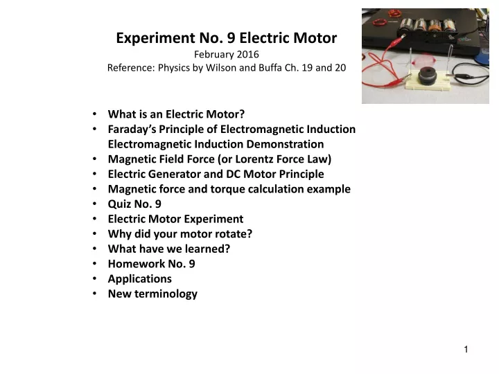
Experiment No. 9 Electric Motor February 2016 Reference: Physics by Wilson and Buffa Ch. 19 and 20. What is an Electric Motor? Faraday ’ s Principle of Electromagnetic Induction Electromagnetic Induction Demonstration Magnetic Field Force (or Lorentz Force Law)

E N D
Experiment No. 9 Electric Motor February 2016 Reference: Physics by Wilson and Buffa Ch. 19 and 20 • What is an Electric Motor? • Faraday’s Principle of Electromagnetic Induction Electromagnetic Induction Demonstration • Magnetic Field Force (or Lorentz Force Law) • Electric Generator and DC Motor Principle • Magnetic force and torque calculation example • Quiz No. 9 • Electric Motor Experiment • Why did your motor rotate? • What have we learned? • Homework No. 9 • Applications • New terminology
F I What is an electric motor? θ B • An electric DC (direct current) motor is a device that converts electrical energy into mechanical energy through the interaction of magnetic fields and current carrying conductors. • The electrical input power is usually in the form of voltage and current, while the mechanical output is a rotating shaft with power defined by rotational speed and torque. • Input power is electric Pelec = VI (V, voltage and I, electric current) • Output power is mechanical Pmech = Tω - Plosses(T, torque and ω, angular velocity)
F I θ B
F I θ B
Oersted Compass Experiment 1820 and Babbage and Herschel Spinning Disk 1824 Every time the electric current was switched on or off, the compass needle moved. Babbage and Herschel demonstrated that if one rotated a horseshoe magnet underneath a pivoted copper disk, the disk would spin. These original experiments created a basis for future development of DC and AC electric motors.
Faraday’s Principle of Electromagnetic Induction 1830 F Faraday showed that if one movedthe magnet in or out of the donut, one could induce or generate a current in the donut coil. Conversely, if one sent a current through the coil, the magnet would move. Faraday hypothesized that both the magnet and the electric coil were each surrounded by an electromagnetic field and the current or motion was produced when one of these fields was changing. However, to get either effect (current or motion) the coil and the magnet, B had to be at right angles. The current, I induced would be a third right angle, perpendicular to both. I θ B
Electromagnetic Induction Demonstration induced by a magnet Regardless of the source of energy the actual conversion to electric energy is accomplished by means of magnetic fields and electromagnetic induction. The discovery of electromagnetic induction by scientist Faraday in 1830 has enabled the development of DC electric motor, AC electric motor, electric generator, transformer and many other applications. Moving the magnet toward the wire loop increases the magnetic flux passing through the loop where an induced current is measured (b). Faraday discovered the electromagnetic induction by experimenting with moving magnetic field lines (magnetic flux) passing through the wire loop.
Electromagnetic Induction by electric current The same observation is demonstrated when changing the magnetic field by (a) increasing or (b) decreasing electric current in another wire loop as shown on the right. Electromagnetic Induction is the creation of the emf (electromotive “force”) whenever the magnetic flux through a coil, loop, or circuit is changed. It is an electric potential measured in volts.
Electric Generator and Electromagnetic Induction θ An electric generator is a device that converts mechanical energy into electrical energy. Most generators produce alternating current in a sinusoidal form (Fig. (b). The rotation of the rotor wire loop causes the magnetic flux through the loop to change thus inducing the electric current in the loop. As the magnetic flux Φ, entering the rotor armature loops changes with time it causes an induced emf E, per Faraday Law which states that E = - N (ΔΦ/Δt) induced emf Φ = BA cosθ = BA cosωt; (ω = θ/t) E = - NBA (Δcosωt)/Δt = (NBAω)sinωt NBAω = E0 (magnitude of maximum emf during cycle) E= E0 sin ωt; (ω, angular velocity 2π/T or 2πf) = T
Faraday Law and Lenz Law Faraday’s Law of Induction states that a magnitude of the induced emf E, is equal to the time based rate of change of the magnetic flux Φ. Φ = BA cosθ [Tm2]; θ = angle between the magnetic field B and area A E = - N (ΔΦ/Δt) induced emf [V] E = - NBA (Δcosωt/Δt); E = NBAωsinωt; E = Eoωsinωt; ω = angular velocity, 2π/T or 2πf Lenz’s Law states that when a change in magnetic flux induces an emf in a coil, loop or circuit, the resulting “induced” current is in such a direction as to create its own “induced” magnetic field to oppose the change in magnetic flux through that loop or coil. (An induced electromotive force (emf) always gives rise to a current whose magnetic field opposes the original change in magnetic flux.)
When an electric current I, passes through a wire that is in a magnetic field B a force F, is exerted upon that wire. It moves! I I The force F, is described by the Lorentz force law and is perpendicular to both the wire and the magnetic field.
DC Electric Motor Principle θ B L • A current-carrying coil in a • magnetic field will rotate but only for half cycle or 180 degrees. The current is reversed every half turn by means of split-ring commutator. • F =B N IL sin θ • When electric current passes through a coil in magnetic field the magnetic force produces a torque t, which turns the motor. • t = 2r x F or B N IA sin θ • (where A = L x 2r) • The rotor coils motion induces a “back emf” force that reduces the current and as its speed of rotation goes up. • Φ = BA cosθ • E = - N (ΔΦ/Δt) • E = Eoωsinωt • Eo = NBAω N r S F I Split-ring commutator • Vm = NBAω + RI The motor rotation in the presence of a magnetic field creates a variable magnetic flux of its own that induces the “back emf” which reduces the electric current.
DC Electric Motor Circuit Diagram In our experiment the electric motor has a rotor (coil) that is electrically powered and rotates in a magnetic field. The moving coil creates a variable magnetic flux which then induces the motor back emf Ebwhich opposesthe 6 V battery voltage Vm. The motor emf reduces the current in the rotor coil and stabilizes the rotor speed. Vm= motor voltage Vm= Eb + RI Eb = back emf Eb = Vm– RI R = rotor resistance Eo = NBAωω = rotor speed “induced” back emf Eb - Eb On motor start up the back emf is zero and the starting current is only limited by the rotor resistance (<1 Ohm in our experiment). As the speed increases the back emf rises and the rotor current drops to approximately 1 to 2 A. + R,rotor + Vm -
Experiment Motor Power Calculations (See the DC Electric Motor Principle slide) Calculate the mechanical power delivered by the rotor shaft with assumption that the speaker magnets have the magnetic field strength B equal to .4 T based on our experience with the solenoid. Assume that the rotational rotor speed (RPM) is 120: Calculate the magnetic force F, on the wire: Bs1 = .4T ; N = 12; d = 4 cm; L = π x d/2 = .063 m; I = 3A; θ = 450 ; sin 45 = .707; F = B N IL sin θ = Bs1N IL sin θ ; F = .4x 12 x .063 x 3 x .707 [TAm] F = .64[TAm = N] Fs1 = .64N Calculate the magnetic torque t: Fs1= .64N; A = π x .022 = 1.3 x10⁻³ [m2] t = B N IA sin θ; t = .64N/.063 m x 1.3 x10-3 [m2] ts1 = 1.32 x 10⁻² Nm Calculate the power P: Power Ps1 = t x ω [Nm x rad/s]; Estimated angular velocity, ω = 120 RPM = 2 rad/sec; = 1.32 x10⁻² [Nm] x 2 [rad/s] x [Ws/Nm]; [Note: 1 W = Nm/s] = 2.64 x 10-2 W x 1,000 mW/W Ps1 = 26.4 mW No. 1: Visualize the dimensions used in the above calcs as they apply to the motor diagram. How do you propose to increase the motor magnetic torque? _________________________ ______________________________________ 20
ExperimentMaterial • 1 clean breadboard (no components on it) • 1 power supply providing 6 volts DC • 5 feet of 22 gage copper wire with varnish insulation • 1 small piece of sand paper • 2 alligator leads • 2 paper clips (large size) • 1 speaker with integral permanent magnet and 1 additional permanent magnet
Make Your Rotor Coil • Using the sandpaper, remove the varnish insulation from 1 to 2 inches of both ends of the copper wire (don’t sand on the table top). • Remove one “D” cell from the battery pack. • Leaving a straight 2-inch lead, wrap the wire around the battery (approximately 12 turns) to create a coil. Leave another 2-inch straight lead at the end. • Slide the copper wire coil off the battery. • Wrap the straight ends of the wire around the coil three times to hold the coil together. • Balance the coil by adjusting the position of the wraps while making the straight pieces the coil’s rotating shaft. • Replace the “D” cell in the battery pack.
Insert paper clips at • h2 and h29 on the • breadboard & support • the coil between them • Put the 2nd magnet on the speaker magnet • Adjust magnets and • coil to minimize the • gap between them • Run with FOUR • battery cells for very short • times (<30 sec) • Careful: do not short • the paper clips with the • speaker housing. Experiment with
What Have We Learned? • An electric motor converts electrical energy into mechanical energy. Its output power is the mechanical power produced by its rotating shaft. • A force called Lorentz Force is exerted on a current carrying wire that moves through a magnetic field. • Rotation of the shaft is caused by the torque exerted on the current carrying wires passing through the magnetic field. • The magnetic field, current flow, and force on the moving wire are mutually perpendicular as described by Flemings right hand rule. • A variation on Lorentz basic formula describes the magnetic force on a current carrying wire and the induced electromotive force in a wire loop moving through a magnetic field to be further studied during the next experiment on generators.
Why did Your Electric Motor Rotate? F =B N IL sin θ t = B N IA sin θ A = πr2; L = πr; θ=450 Force B Wire Wound Coil Current I θ Field F Rotor Shaft F B Battery 6V + I Paper Clip x 2 Alligator Leads RED Alligator Leads BLACK - N N Alligator Leads BLACK Magnet Breadboard S The Force “F” that Moves the Rotor is Proportional to the Magnetic Field Force “B” and Electric Current “I” in the Coil
Motor Power Calculations (See the torque calcs) Calculate the mechanical power delivered by the rotor shaft with assumption that the speaker magnets have the magnetic field strength B equal to .4 T based on our experience with the solenoid. Assume that the rotational rotor speed (RPM) is 120: Calculate the magnetic force F, on the wire: Bs1 = .4T ; N = 12; d = 4 cm; L = π x d/2 = .063 m; I = 3A; θ = 450 ; sin 45 = .707; F = B N IL sin θ = Bs1N IL sin θ ; F = .4x 12 x .063 x 3 x .707 [TAm] F = .64[TAm = N] Fs1 = .64N Calculate the magnetic torque t: Fs1= .64N; A = π x .022 = 1.3 x10⁻³ [m2] t = B N IA sin θ; t = .64N/.063 m x 1.3 x10-3 [m2] ts1 = 1.32 x 10⁻² Nm Calculate the power P: Power Ps1 = t x ω [Nm x rad/s]; Estimated angular velocity, ω = 120 RPM = 2 rad/sec; = 1.32 x10⁻² [Nm] x 2 [rad/s] x [Ws/Nm]; [Note: 1 W = Nm/s] = 2.64 x 10-2 W x 1,000 mW/W Ps1 = 26.4 mW
New Terminology • Ferromagnetic- A ferromagnetic material is one that has magnetic properties similar to those of iron. A “hard” iron once magnetized retains permanently the magnetic properties. A “soft” iron remains magnetized only while the magnetic field is induced by electric current. • Magnetic field- It is created by an electric current (electromagnet) or the by an already permanently magnetized material having the spinning motion of electrons (permanent). A magnetic field strength, H (Amps per meter) is a mathematical description of the magnetic influence of electric currents and magnetic materials. • Magnetic Permeability- the measure of material’s ability to support formation of a magnetic field. It is a degree of magnetization that a material obtains in response to an applied magnetic field. B = μH, magnetic flux density B, measured in Tesla or Gauss and specified by its direction and magnitude. μ0 is permeability of the free space; μ is permeability of a ferromagnetic material; B= F/qv ; F is the force of motion, N; q is the electric charge, C; v is charge velocity, m/s; • Ampère- Scientist Ampère deduced from Oersted’s experiment that electric current in a wound coil exhibits all properties of an “electromagnet”. • Electromagnet- Magnetic field that is created by the movement of electrons in an electrical field. It attracts other ferromagnetic material. • Solenoid- The term refers specifically to a long, loop of wire, often wrapped around a metallic core, which produces a uniform magnetic field in a volume of space. • Ampere-turns- A magneto-motive force of a current of one Ampère flowing in a single-turn loop. • Fleming’s Right Hand Rule - It sets the vector relationship between the force (motion), electric current (electric charge velocity and direction) and the magnetic field. • Lorentz force- When a wire carrying electrical current is placed in a magnetic field, each of the moving charges, which comprise the current experience the Lorentz force. The wire then moves. • Electromotive force EMF- The magnetic force (qv x B) is responsible for motional electromotive force (EMF). When a conductor is moved through a magnetic field, the magnetic force tries to push electrons through the wire, and this creates the EMF. The EMF is due to the motion of the wire in a magnetic field.
SI Electromagnetism Units Symbol Name Unit SI Conversion I Electric current Ampere A = C/s q Electric charge Coulomb C = As E Electromotive force, Potential difference Volt J/C = (kgms2/A)/s3 ρResistivity Resistivity Ωm P Electric power Watt W = kgms2/s3 E Electric field strength Volt per meter V/m H Magnetic field strength Ampere per meter A/m B Magnetic flux density, Induction (F/qv) Tesla T = Wb/m2 μ Permeability henry per meter Tm/A= H/m = kgm/(As) μ0 Permeability of free space 4 π x 10-7N/A2 F Force of motion N 1 N = 1 kg m/s2 v Velocity m/s Resistance Ohm V/A = 1 Ω = 1 kg·m2·s-3·A-2 in Inch Inch 0.0254 m or 25.4 mm T Tesla Tesla Vs/m2 = N/Am = Wb/ms2 N Newton Newton Kgm/s2 Wb Weber Weber 1 V·s = 1 T·m2 = 1 J/A; J Joule1Nm; 1kgm2/s2 ; 2.78 x 10⁻⁷ kWh; 2.39 x 10⁻⁴ kcal; 9.48 x10⁻⁴ BTU P Mechanical power 1hp 550 ft-lb/s = 1 W Kg Kilogram mass 1.0 kg x 9.8m/s2 1N Ω
Faraday’s Law Applications Ground-fault Circuit Interrupter (GFCI) Tape-recorder head Tape-recorder head Other applications: Electric Generators and Back emf Electric Motor Back emf Electric current transmission cables skin effect Electromagnetic Waves (Antenna) Transformer Electromagnetic Braking and Mass Transit