Download

1 / 5
50 likes | 81 Views
Wind power is the most reliable and developed renewable energy source. This paper gives a study on power flow control of a grid connected Doubly Fed Induction Generator DFIG wind turbine. Doubly Fed Induction Generator DFIG has widely used for large wind farms. A back to back converter is incorporated between the stator and the rotor windings of a DFIG, in order to obtain variable speed operation. The controller design methodology is presented and active and reactive power is verified. The main objective of the paper is to control the flow of the active and reactive powers produced by the DFIG based wind energy conversion system. In order to decouple of active and reactive powers generated, the vector control method is applied. A vector control strategy with stator flux orientation is applied to both the grid side converter and the rotor side converter for the independent control of active and reactive powers produced by the DFIG based wind energy conversion system. Simulation results on a 2MW DFIG system are provided to demonstrate the proposed control strategy and the variations of active and reactive power, rotor speed, and converter dc link voltage. Hnin Yu Wai | Theingi Htun | Myo Win Kyaw "Active and Reactive Power Control of DFIG Based Grid Connected Wind Energy System" Published in International Journal of Trend in Scientific Research and Development (ijtsrd), ISSN: 2456-6470, Volume-3 | Issue-5 , August 2019, URL: https://www.ijtsrd.com/papers/ijtsrd26509.pdf Paper URL: https://www.ijtsrd.com/engineering/electrical-engineering/26509/active-and-reactive-power-control-of-dfig-based-grid-connected-wind-energy-system/hnin-yu-wai<br>

E N D
International Journal of Trend in Scientific Research and Development (IJTSRD) Volume 3 Issue 5, August 2019 Available Online: www.ijtsrd.com e-ISSN: 2456 – 6470 Active and Reactive Power Control of DFIG Based Grid Connected Wind Energy System Hnin Yu Wai1, Theingi Htun2, Myo Win Kyaw2 1Department of Electrical Power Engineering, West Yangon Technological University, Yangon, Myanmar 2Department of Electrical Power Engineering, Technological University Mandalay, Mandalay, Myanmar How to cite this paper: Hnin Yu Wai | Theingi Htun | Myo Win Kyaw "Active and Reactive Power Control of DFIG Based Grid Connected Wind Energy System" Published in International Journal of Trend in Scientific Research and Development (ijtsrd), ISSN: 2456- 6470, Volume-3 | Issue-5, August 2019, https://doi.org/10.31142/ijtsrd26509 Copyright © 2019 by author(s) and International Journal of Trend in Scientific Research and Development Journal. This is an Open Access article distributed under the terms of the Creative Commons Attribution License (CC (http://creativecommons.org/licenses/by /4.0) To solve the problem of energy’s shortage and improve environmental quality, wind power is used to produce electricity by a lot of countries [3]. Wind turbines can either operate at fixed or variable speed. For a fixed speed wind turbine the generator is directly connected to the electrical grid. For a variable speed wind turbine the generator is controlled by a power electronic converter. The main advantages of using variable speed operation of the wind turbine are the possibility to reduce stresses on the mechanical structure, acoustic noise reduction and the possibility to control active and reactive power. Unbalance in wind energy is highly impacting the energy conversion and this problem can be overcome by using a Doubly Fed Induction Generator (DFIG) [2]. Doubly fed wound rotor induction machine with vector control is very attractive to the high-performance variable speed drive and generating applications [3]. The wind is highly in nature, a variable speed DFIG based Wind Energy Conversion System (WECS) offer many advantages compared to the fixed speed squirrel cage induction generators. Due to variable speed operation, the total energy output is much more in case of DFIG based WECS. Nowadays, most large wind turbines are based on variable speed operation with pith control using a DFIG. The major advantages of the DFIG are that the power electronic equipment used that handles a fraction of (20- 30%) total system power. The back to back converter consists of two ABSTRACT Wind power is the most reliable and developed renewable energy source. This paper gives a study on power flow control of a grid-connected Doubly-Fed Induction Generator (DFIG) wind turbine. Doubly-Fed Induction Generator (DFIG) has widely used for large wind farms. A back-to-back converter is incorporated between the stator and the rotor windings of a DFIG, in order to obtain variable speed operation. The controller design methodology is presented and active and reactive power is verified. The main objective of the paper is to control the flow of the active and reactive powers produced by the DFIG based wind energy conversion system. In order to decouple of active and reactive powers generated, the vector control method is applied. A vector control strategy with stator flux orientation is applied to both the grid-side converter and the rotor-side converter for the independent control of active and reactive powers produced by the DFIG based wind energy conversion system. Simulation results on a 2MW DFIG system are provided to demonstrate the proposed control strategy and the variations of active and reactive power, rotor speed, and converter dc-link voltage. KEYWORDS: Doubly-Fed Induction Generator, back-to-back converter, Active and Reactive Power Control, Vector control I. INTRODUCTION Wind power is one of the most important and promising sources of renewable energy all over the world. It also is a permanent source without exploring and transporting. IJTSRD26509 pp.961-965, BY 4.0) converters i.e. Grid-Side Converter (GSC) and Rotor-Side Converter (RSC) connected back to back through a dc-link capacitor for energy storage purpose [4]. In this paper, a control strategy is presented for DFIG. The vector control of DFIG based wind energy conversion system for efficient and good performance is discussed. A vector control strategy can be used for decoupled control of active and reactive power drawn from the supply. In this paper, we study the control strategy for the DFIG and the mathematical models. The complete MATLAB/SIMULINK model of a 2MW DFIG generation system is built. From the analysis of the simulation result, we can realize that the DFIG active power output will keep varying with the change of the wind speed. Wind power is one of the most important and promising sources of renewable energy all over the world. It also is a permanent source without exploring and transporting. To solve the problem of energy’s shortage and improve environmental quality, wind power is used to produce electricity by a lot of countries [3]. Wind turbines can either operate at fixed or variable speed. For a fixed speed wind turbine the generator is directly connected to the electrical grid. For a variable speed wind turbine the generator is controlled by a power electronic converter. The main advantages of using variable speed operation of the wind turbine are the possibility to reduce stresses on the mechanical structure, acoustic noise reduction and the @ IJTSRD | Unique Paper ID – IJTSRD26509 | Volume – 3 | Issue – 5 | July - August 2019 Page 961
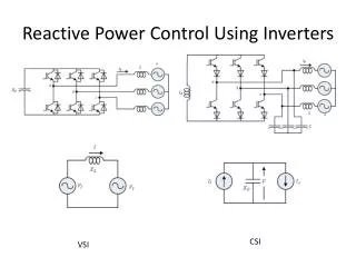
International Journal of Trend in Scientific Research and Development (IJTSRD) @ www.ijtsrd.com eISSN: 2456-6470 possibility to control active and reactive power. Unbalance in wind energy is highly impacting the energy conversion and this problem can be overcome by using a Doubly Fed Induction Generator (DFIG) [2]. Doubly fed wound rotor induction machine with vector control is very attractive to the high-performance variable speed drive and generating applications [3]. The wind is highly in nature, a variable speed DFIG based Wind Energy Conversion System (WECS) offer many advantages compared to the fixed speed squirrel cage induction generators. Due to variable speed operation, the total energy output is much more in case of DFIG based WECS. Nowadays, most large wind turbines are based on variable speed operation with pith control using a DFIG. The major advantages of the DFIG are that the power electronic equipment used that handles a fraction of (20- 30%) total system power. The back to back converter consists of two converters i.e. Grid-Side Converter (GSC) and Rotor-Side Converter (RSC) connected back to back through a dc-link capacitor for energy storage purpose [4]. In this paper, a control strategy is presented for DFIG. The vector control of DFIG based wind energy conversion system for efficient and good performance is discussed. A vector control strategy can be used for decoupled control of active and reactive power drawn from the supply. In this paper, we study the control strategy for the DFIG and the mathematical models. The complete MATLAB/SIMULINK model of a 2MW DFIG generation system is built. From the analysis of the simulation result, we can realize that the DFIG active power output will keep varying with the change of the wind speed. II. DFIG FOR WIND ENERGY CONVERSION Wind Energy Conversion System (WECS) converts wind energy into useful mechanical energy in a wind-turbine that is used as the prime-mover to power an electrical (Doubly Fed Induction Generator [DFIG]) generator. The WECS basically consists of two major components; (i) turbine and associated control including the gearbox, and (ii) electrical (DFIG including the rotor converter system and associated control). A simplified block diagram of a wind energy conversion system (WECS) using DFIG is illustrated in figure 1. It consists of a wind turbine, a gearbox, doubly-fed induction generator, and a rotor side converter and a grid-side converter. The DFIG stator winding is directly connected to the grid whereas its rotor windings are connected by a back- to-back three-level voltage source converters. By controlling the rotor and grid side converters, the DFIG characteristics can be adjusted so as to achieve the maximum of effective power conversion or capturing power. These converters are usually controlled by utilizing vector control techniques, capability for a wind turbine and to control its power flow from DFIG to grid with less fluctuation [5]. Figure1. Doubly-Fed Induction Generator Driven by a Wind Turbine DFIG Modeling The stator and rotor a-, b-, c- phase voltage equations and flux equations can be transformed to the d-q axis. Based on the d – q equivalent circuit model of the induction machine shown in Figure 2 [6][7], Figure 2 Dynamic Equivalent Circuit of DFIG (a) q-axis Equivalent Circuit (b) d-axis Equivalent Circuit The classical governing equations of the DFIG in a d-q synchronously rotating reference frame can be written as following from above figure 2. qs dψ qs is R qs v ds ds ds dψ qr ir R qr v ω ψ e ds dt dψ v R is ω ψ e qs dt qr (ω ω )ψ dr e r dt dψ dr v R ir (ω ω )ψ qr dr dr e r dt (1) The flux equations are qs i ls qs L ds i lr qr ψ L L (i i ) L is L i m L qs (i qr qs L m qr L ψ i i ) is i m m ls ds qr ds dr ) ds dr ψ L L (i i L ir L i m qs qr qr m qs @ IJTSRD | Unique Paper ID – IJTSRD26509 | Volume – 3 | Issue – 5 | July - August 2019 Page 962
International Journal of Trend in Scientific Research and Development (IJTSRD) @ www.ijtsrd.com eISSN: 2456-6470 By substituting equation (7) into equation (1), the rotor voltage can be expressed i r σL dr dr ψ L i L (i i ) L ir L i m m dr lr dr ds dr dr ds (2) Where, s ω ω dr v R ir ω σL ir s qr dt ω ω (8) e r , 2 m σL ir L i i = the rotational speed of the synchronous reference frame, = the slip frequency and qr e dr ms v R ir σL ω (s ) qr qr r dt L s (9) ω s r 2m L σ 1 Where, ω Rs, Rr = the electrical speed measured in [rad/s]. = equivalent resistances of stator and rotor windings L, r, Ls Lm = self and mutual inductance of stator and rotor windings III. ACTIVE AND REACTIVE POWER CONTROL FOR DFIG A.Rotor-Side Converter (RSC) The main task of the rotor-side converter is to control the machine i.e., active and reactive powers of the DFIG. The active and reactive powers which are delivered from the DFIG to the grid are controlled by means of controlling the rotor currents of the DFIG [6]. The diagram of the vector control of the rotor-side converter can be obtained from the below analysis is shown in figure 3. In the stator-flux oriented reference frame, the d-axis is aligned with the stator flux linkage vector the flux equation is ψs the flux equation is [1] ms m s ds , To keep the stator flux ψs constant, the voltage equations are d ds L L s r Figure3. The vector control diagram of the rotor-side converter ψ 0 ψ ψ L i qs (3) B.Grid-Side Converter (GSC) The grid-side converter balance and delivers the power between the three-phase grid and the DC link capacitor. The DC-link power should be equal to the grid-side converter’s output power. The grid-side converter is used to regulate the voltage of the DC bus capacitor. The diagram of the vector control of the grid-side converter can be obtained from the below analysis is shown in figure 4. Under the synchronously rotating frame, the d-axis aligns with the grid voltage [1]. The grid voltage components are Vd = Constant Vq = 0 The active power and reactive powers equation is 3 ) qiq v d d 2 3 ) d d 2 According to the above equations, we assume two compensation term ud1 and uq1, di L d d1 q di L q Ri q1 Applying the above compensation terms ud and uq, we can obtain the reference voltage ud* and uq* v q Li e (ω d1 d v ψ 0 s dt v ω ψ V (4) qs e s s Where, Vs = the space vector amplitude of stator voltages The active and reactive powers of the stator can be derived as 3 s P (10) (v i v i ) qs qs ds ds 2 3 rP (v i v i d d 2 3 (11) Q (v i v i ) s qs qs ds ds 3 2 Q (v qi v iq v i (5) r d q 2 (12) The equivalent stator magnetizing current can be considered a constant, i.e. V s ψ ms i By substituting equation (5) into equation (2), m L ds m L qs i s d u Ri L L ω s (6) m 1 dt u dt (13) i (i i ) ms dr L s i qr * L u u ) s (7) d @ IJTSRD | Unique Paper ID – IJTSRD26509 | Volume – 3 | Issue – 5 | July - August 2019 Page 963
International Journal of Trend in Scientific Research and Development (IJTSRD) @ www.ijtsrd.com eISSN: 2456-6470 *q u u (ω Li ) e q1 d (14) Figure6. Back-to-Back Converter Figure 6 showing the model of a back-to-back converter of DFIG. Vector control is one of the most commonly used methods applied to control the flow of active and reactive power between the stator and the grid. The vector control technique can be applied to both RSC and GSC. Typically, the RSC controller aims to control the stator active and reactive power flow by controlling the rotor current components on d-q axis ( qr i , dr is to maintain the DC-link voltage constant regardless the magnitude and direction of the rotor power. VI. SIMULATION RESULTS Simulation of the proposed control strategy for the DFIG- based generation system using Matlab Software. The DFIG based wind energy conversion system was simulated, for the active and reactive power control on the Matlab/Simulink platform. In this section, the simulation results for the system operation are shown. Results are presented to demonstrate its behavior at variable wind speed. The waveforms for voltage, current, active and reactive powers, rotor speed and dc-link voltage are presented for different wind speed. Figure4. The vector control diagram of the grid-side converter i ) while the objective of the GSC controller IV. SYSTEM PARAMETERS TABLE I. PARAMETERS OF THE SIMULATED DFIG Parameters Rated power, n Rated voltage, V Frequency, f Number of pairs of poles, p Stator resistance, R Values 2 MW 400 V 50 Hz 3 0.023 pu P s L Stator leakage inductance, 0.18 pu ls 0.016 pu R Rotor resistance, r Rotor leakage inductance, L 0.16 pu 12 m/s 120*103 var 2.9 pu 1000 rpm 7-10-12m/s lr Rated wind speed Filter capacitor Magnetizing inductance, m Speed Wind speed variation L V. SIMULINK MODELS OF THE SYSTEM Figure7. Voltage and Current at Bus400 Figure5. Simulink Model of DFIG Based Grid Connected Wind Energy System Figure 5 shown Simulink Model of DFIG Based Grid Connected Wind Energy MATLAB/SIMULINK. System by using the Figure8. Active and Reactive Power at Bus400 @ IJTSRD | Unique Paper ID – IJTSRD26509 | Volume – 3 | Issue – 5 | July - August 2019 Page 964
International Journal of Trend in Scientific Research and Development (IJTSRD) @ www.ijtsrd.com eISSN: 2456-6470 power output near zero regardless of the wind speed fluctuation. The voltage and current measurement at B33 (33kV bus bar) for grid-connected wind power system shown in figure 11 maintained at the rated value at t=5s. The active and reactive power output at B400 of the DFIG is shown in figure 12. The active power output is stable with a magnitude of 2MW at t=0.5s. Figure 13 shown the DC link voltage and speed at the DC link voltage varies with the wind speed fluctuation. The active and reactive power for the turbine shown in figure 14 in which the variation of the output power with the wind speed fluctuation. VII. CONCLUSION This research represented an active and reactive power flow control analysis of converters in wind turbines based grid- connected wind energy system. Power converters are usually controlled a utilizing vector control technique which allows the control of both active and reactive power flow to the grid. As a result the active and reactive powers are controlled by using the vector control principle which yields better results. Due to the advances in power electronics, it is advantaged to use the doubly-fed induction generator system with fixed speed connected to the electrical grid through a back-to-back converter, that improving the efficiency of the power conversion. A detail simulation model of a DFIG-based wind turbine system is developed for the 2MW wind turbine connected to the power grid. Modeling and simulation results of a DFIG based grid-connected wind energy system by using vector control concept are presented in this paper. The system MATLAB/SIMULINK software. REFERENCES [1]Hung-Cheng Chen, Po-Hung Chen, “Active and Reactive Power Control of a Doubly Fed Induction Generator,” Appl. Mach. Inf, Sci. 8, no 1, Apr. 2014. Figure9. Voltage and Current at Bus33 Figure10. Active and Reactive Power at Bus33 was developed in [2]Sateesh Sukhavasi, “Active and Reactive Power Control of DFIG”, International Journal of Current Trends in Engineering and Technology, vol. 1, issue. 1, Nov. 2014. [3]Akshay CONVERSION SYSTEM CONNECTED TO GRID,” International Journal of Technical Research and Applications, vol. 1, issue 3, pp. 15-24, Aug. 2013. Kumar, “DFIG-BASED WIND POWER Figure11. DC Link Voltage and Rotor Speed [4]Sai Sindhura K, G. Srinivas Rao, “Control and Modeling of Doubly Fed Induction Machine for Wind Turbines,” IJERA, vol. 3, issue. 6, pp. 532-538, Nov-Dec. 2013. [5]Shilpa Mishra, Sandeep Shukla, Shimi. S. L, “Performance Analysis and Limitations of Grid Connected DFIG Wind Turbine under Voltage Sag and 3-Phase Fault,” International Journal of Engineering Research and Development, vol. 10, issue. 8, pp. 51-62, Aug. 2014. [6]Tarek Massaud, “Modeling, Analysis, Control and Design Application Guidelines of Doubly Fed Induction Generator (DFIG) for Wind Power Applications,” Ph.D. dissertation, Department of Electrical Engineering and Computer Science. Figure12. Active and Reactive Power For Wind Turbine The voltage and current measurement at B400 (400V bus bar) for grid-connected wind power system shown in figure 9 maintain at with wind speed variation. The active and reactive power output at B400 of the DFIG is shown in figure 10. The wind speed arrives at rated speed 12m/s at t=0.5s, at which the active power output is 1.7MW. The zero-reactive- control in the back-to-back converter keeps the reactive [7]Nidhish G Mishra, A. A. Shaikh, “Simulation of Active and Reactive Power Control of DFIG,” American Journal of Engineering Research (AJER), vol.3, issue.4, pp.76- 83. @ IJTSRD | Unique Paper ID – IJTSRD26509 | Volume – 3 | Issue – 5 | July - August 2019 Page 965