Download
1 / 4
50 likes | 54 Views
In highly populated countries, people lose their lives because of accidents and poor emergency facilities every day. These lives could have been saved if medical facilities are provided at the right time. This thesis implies a system which is a solution to this drawback, when a vehicle meets with an accident immediately, accelerometer module detects the signal, and it is sent to the Arduino microcontroller programmed by C programming language. Arduino sends an alert message through the GSM module including the location to the police station or a rescue team. So the police can immediately trace the location through the GPS modem after receiving the information. LCD is used to display location message from GPS module. The system is simulated and practically designed by the use of required hardware components and the results are satisfied with the expectation. Yu Yu Mon Win | Moe Myint Aung | Thin Thin "Accident Detection System using Arduino Uno" Published in International Journal of Trend in Scientific Research and Development (ijtsrd), ISSN: 2456-6470, Volume-3 | Issue-5 , August 2019, URL: https://www.ijtsrd.com/papers/ijtsrd27840.pdf Paper URL: https://www.ijtsrd.com/computer-science/other/27840/accident-detection-system-using-arduino-uno/yu-yu-mon-win<br>

E N D
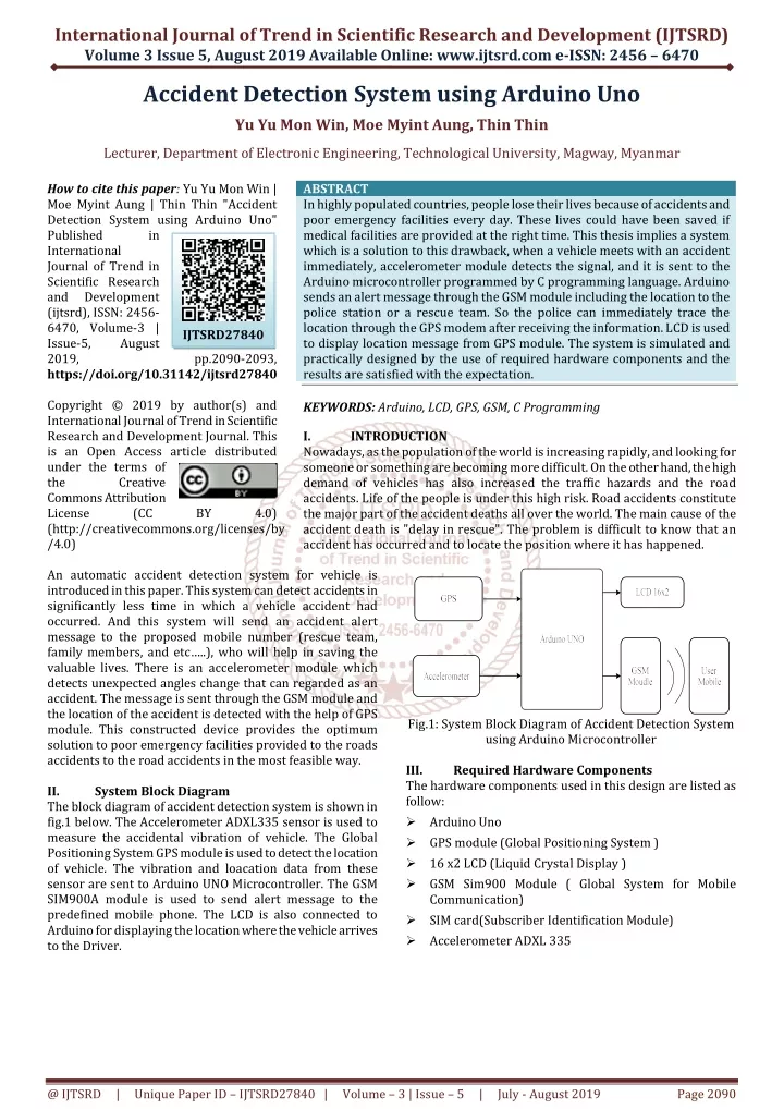
International Journal of Trend in Scientific Research and Development (IJTSRD) Volume 3 Issue 5, August 2019 Available Online: www.ijtsrd.com e-ISSN: 2456 – 6470 Accident Detection System using Arduino Uno Yu Yu Mon Win, Moe Myint Aung, Thin Thin Lecturer, Department of Electronic Engineering, Technological University, Magway, Myanmar How to cite this paper: Yu Yu Mon Win | Moe Myint Aung | Thin Thin "Accident Detection System using Arduino Uno" Published in International Journal of Trend in Scientific Research and Development (ijtsrd), ISSN: 2456- 6470, Volume-3 | Issue-5, August 2019, https://doi.org/10.31142/ijtsrd27840 Copyright © 2019 by author(s) and International Journal of Trend in Scientific Research and Development Journal. This is an Open Access article distributed under the terms of the Creative Commons Attribution License (CC (http://creativecommons.org/licenses/by /4.0) An automatic accident detection system for vehicle is introduced in this paper. This system can detect accidents in significantly less time in which a vehicle accident had occurred. And this system will send an accident alert message to the proposed mobile number (rescue team, family members, and etc…..), who will help in saving the valuable lives. There is an accelerometer module which detects unexpected angles change that can regarded as an accident. The message is sent through the GSM module and the location of the accident is detected with the help of GPS module. This constructed device provides the optimum solution to poor emergency facilities provided to the roads accidents to the road accidents in the most feasible way. II. System Block Diagram The block diagram of accident detection system is shown in fig.1 below. The Accelerometer ADXL335 sensor is used to measure the accidental vibration of vehicle. The Global Positioning System GPS module is used to detect the location of vehicle. The vibration and loacation data from these sensor are sent to Arduino UNO Microcontroller. The GSM SIM900A module is used to send alert message to the predefined mobile phone. The LCD is also connected to Arduino for displaying the location where the vehicle arrives to the Driver. ABSTRACT In highly populated countries, people lose their lives because of accidents and poor emergency facilities every day. These lives could have been saved if medical facilities are provided at the right time. This thesis implies a system which is a solution to this drawback, when a vehicle meets with an accident immediately, accelerometer module detects the signal, and it is sent to the Arduino microcontroller programmed by C programming language. Arduino sends an alert message through the GSM module including the location to the police station or a rescue team. So the police can immediately trace the location through the GPS modem after receiving the information. LCD is used to display location message from GPS module. The system is simulated and practically designed by the use of required hardware components and the results are satisfied with the expectation. KEYWORDS: Arduino, LCD, GPS, GSM, C Programming I. INTRODUCTION Nowadays, as the population of the world is increasing rapidly, and looking for someone or something are becoming more difficult. On the other hand, the high demand of vehicles has also increased the traffic hazards and the road accidents. Life of the people is under this high risk. Road accidents constitute the major part of the accident deaths all over the world. The main cause of the accident death is "delay in rescue". The problem is difficult to know that an accident has occurred and to locate the position where it has happened. IJTSRD27840 pp.2090-2093, BY 4.0) Fig.1: System Block Diagram of Accident Detection System using Arduino Microcontroller III. Required Hardware Components The hardware components used in this design are listed as follow: Arduino Uno GPS module (Global Positioning System ) 16 x2 LCD (Liquid Crystal Display ) GSM Sim900 Module ( Global System for Mobile Communication) SIM card(Subscriber Identification Module) Accelerometer ADXL 335 @ IJTSRD | Unique Paper ID – IJTSRD27840 | Volume – 3 | Issue – 5 | July - August 2019 Page 2090
International Journal of Trend in Scientific Research and Development (IJTSRD) @ www.ijtsrd.com eISSN: 2456-6470 They are described in Figure 2. Fig2. Collected Devices before Installation A.Overview of the System Fig 3 Overall Circuit of the System The pin assignment for the complete circuit is shown in table. Table 1 Pin Assignments Arduino Pins A3 A4 A5 D2 D3 D10 D4 D5 D6 D7 D8 D9 Pins of Components Pin “X” of ADXL 335 Pin “Y” of ADXL335 Pin “Z” of ADXL335 Tx Pin of GSM Module Rx Pin Of GSM Module Tx Pin of GPS Module RS Pin of LCD EN Pin of LCD D4 Pin of LCD D5 Pin of LCD D6 Pin of LCD D7 Pin of LCD @ IJTSRD | Unique Paper ID – IJTSRD27840 | Volume – 3 | Issue – 5 | July - August 2019 Page 2091
International Journal of Trend in Scientific Research and Development (IJTSRD) @ www.ijtsrd.com eISSN: 2456-6470 B.Flowchart of the System Start Device Switch on (GPS, GSM,LCD,ACCELEROMETER) GPS Initializing No GPS Range Finding Module Accelerometer Ready NO Accelerometer sense X,Y,Z direction GPS Range Found GPS is Ready Module Connected ? YES Show Longitude and Latitude on LCD Get GPS Data Send the Vibration values to MPU Finding Network NO GPS is Ready Network Found? Exceed the assigned value? NO YES YES GSM is Ready Send SMS via GSM module to the user Show Longitude and Latitude on User’s Mobile End Fig 4 System Flowchart C.Operation of The System In this design, Arduino is used for controlling the whole process with a GPS receiver and GSM module. GPS receiver is used for detecting the coordinate of the vehicle, GSM module is used for sending the alert SMS with the coordinates. Accelerometer namely ADXL 335 is used for detecting accident or sudden change in any axis. An LCD 16x2 is also used for displaying status of the system. After the code is being uploaded to the Arduino, the system is ready to start. Now, there is unexpected vibration or the axis value of accelerometer is changed,the Arduino inform the accident detection to the GSM module. The data from GPS module is read by Arduino and the coordinate is get by extracting $GPMRC String. The location is continuously displays on LCD. But The GSM only sends SMS to the predefined number such as the police, ambulance, or family member with the location coordinates of accident place when the unexpected vibration occurs . The GSM module can communicate with the network by using AT commands. The main requirements for this circuit are initializations of GSM and GPS module. When they are correctly initialized, the system can operate to get desired results. IV. Tests and Results There are four individual tests before connecting the overall circuit design. They are: Reading data from ADXL335 Location data Reading from GPS Module Sending SMS message by GSM SIM900A Module Display on LCD A.Reading Analog Data From ADXL335 The Arduino read data from ADXL335 accelerometer by using the code shown in Figure 5. Fig5. Acceleration Test and Simulation Result B.Location Data Reading from GPS Module Fig6. GPS Test using Arduino The following command is used to get GPS data. While (gps.avaiable()>0) {byte gpsData=gps.read(); Serial.write (gpsData=gps.read()); @ IJTSRD | Unique Paper ID – IJTSRD27840 | Volume – 3 | Issue – 5 | July - August 2019 Page 2092
International Journal of Trend in Scientific Research and Development (IJTSRD) @ www.ijtsrd.com eISSN: 2456-6470 The location can be get from above $GPRMC String. This String means $ represents "NMEA Data" GP represents "GPS position" RMC represents "Recommended Minimum sentence C" 022527.00 represents "HHMMSS.SS" (Hours, Minutes, Second) A represents "Status // A=active" 2414.85025 represents "DDMM.MMMMM" ( latitude Degree, Minutes) N represents "Direction N=North, S= South" 09714.28923 represents " DDDMM.MMMMM" ( Longitude Degree, Minutes) E represents "Direction E= East, W=West". C.Sending SMS message by GSM SIM900A Module By using the AT commands described in Table 2 GSM module is tested. Table2. AT Commands Commands ATA Answer Command ATD Dial Command AT+CMGS Send SMS message AT+CMGF Select SMS Message format AT+CNMI New SMS Message indication AT+CPIN Description Check Pin VI. Nowadays, to provide a suitable safety of road accident preventing and detection system is becoming one of the most important things for the future generation. There is an increasing the death of people because of road accidents. The demand for this process is to save life just on time after the accident has occurred. There are so many ways to know the location after the accident has occurred. This GPS and GSM based automatic accident detection system is also one of the less delay time and the most effective system for this present days. REFERENCES [1]Araya D.S and Athulya C.K Accident Alert and Tracking Using Arduino, Dept. of Electrical and Electronics Engineering, Mar Baselios Institute of Technology and Science, Nellimattom, Kerala, India, (2018). Conclusion and Discussion Figure 7. GSM Test D.Displaying on LCD Interfacing between LCD and Arduino is also tested.The 16 x 2 LCD display is command by four bit mode. [2]Waleed Mohy Eldeen Ibrahem: Accident Detection and Reporting, System using GPS and GSM Module, Almughtaribeen University College of Engineering, Department of Communication Fifth Year Bachelors, (2017). [3]Jonathan Vail: Global Positioning System, U.S Enviromental Protection Angency Science and Ecosystem Support Division Athens, Georgia, (2015). [4]Kommineni Rakesh: Vehicle Tracking and Accident Alert System, National Institute of Technology Rourkela, (2014). Figure8. View of LCD Test Final Installation and Tests Since the individual tests are satisfied, then all devices are carefully connected and upload the complete code on Arduino. The maximum limit acceleration is predefined for accident detection. When accident is detected, the message is sent as shown in Figure. V. [5]Automatic Traffic Accident Detection and Alert System International Journal Technology Exploration an d Learning (IJTEL), Volume 1, Issue 1, (August 2012). @ IJTSRD | Unique Paper ID – IJTSRD27840 | Volume – 3 | Issue – 5 | July - August 2019 Page 2093