Download
1 / 3
30 likes | 35 Views
Temperature control is defined as to maintain the temperature at desired set point. It is widely used process. In modern era temperature control is an important factor as it has many applications. Automatic temperature control is the best way to control the temperature automatically in any electrical appliance. This method has improved significantly in temperature control as it functions with least or minimal manual intervention. The result shows the temperature is controlled in an effective and precise manner. In addition, it was observed that Automatic Temperature Controlled Air Cooler was cost efficient as compared to the conventional air cooler. Vijay Kumar Gupta | Himanshu Singh | Kunwar Utkarsh | Ankit Kumar | Abhinav Kumar Vishwakarma | Mohak Gupta "Automatic Temperature Controlled Air Cooler: Design, Assembly and Testing" Published in International Journal of Trend in Scientific Research and Development (ijtsrd), ISSN: 2456-6470, Volume-3 | Issue-3 , April 2019, URL: https://www.ijtsrd.com/papers/ijtsrd23327.pdf Paper URL: https://www.ijtsrd.com/engineering/mechanical-engineering/23327/automatic-temperature-controlled-air-cooler-design-assembly-and-testing/vijay-kumar-gupta<br>

E N D
International Journal of Trend in Scientific Research and Development (IJTSRD) Volume: 3 | Issue: 3 | Mar-Apr 2019 Available Online: www.ijtsrd.com e-ISSN: 2456 - 6470 Automatic Temperature Controlled Air Cooler: Design, Assembly and Testing Vijay Kumar Gupta1, Himanshu Singh2, Kunwar Utkarsh2, Ankit Kumar2, Abhinav Kumar Vishwakarma2, Mohak Gupta2 1Assistant Professor, 2Student 1,2ABES Engineering College, Ghaziabad, Uttar Pradesh, India How to cite this paper: Vijay Kumar Gupta | Himanshu Singh | Kunwar Utkarsh | Ankit Kumar | Abhinav Kumar Vishwakarma | Mohak Gupta "Automatic Temperature Controlled Air Cooler: Design, Assembly and Testing" Published in International Journal of Trend in Scientific Research and Development (ijtsrd), ISSN: 2456- 6470, Volume-3 | Issue-3, April 2019, pp.1334-1336, URL: https://www.ijtsrd.c om/papers/ijtsrd23 327.pdf Copyright © 2019 by author(s) and International Journal of Trend in Scientific Research and Development Journal. This is an Open Access article distributed under the terms of the Creative Commons Attribution License (CC BY 4.0) (http://creativecommons.org/licenses/ by/4.0) 1.INTRODUCTION A temperature control system has a programmable thermostat that keeps the environment at a desired temperature. The advantage of having an automatic temperature control system over a common thermostat is that it saves energy and cost by automatically maintaining different temperatures at various instant. It has a closed loop feedback system having a control loop, including thermal sensors, control program and actuators/effectors, and is arranged in such a manner so as to regulate a variable temperature at a set point or reference value defined by end user. A host of analysis of temperature control have appeared in literature [1-4]. These analysis employs the use of closed loop temperature control system which works according to the temperature of the environment. It was shown experimentally by Ahmad Faris Bin Zulkifli [1] that using temperature sensor one can control the room temperature of a region without any human intervention. Temperature control and sensor systems follows a conventional pattern. The sensor device senses the temperature and passes its analog signal to the Arduino unit for the micro-controller to ABSTRACT Temperature control is defined as to maintain the temperature at desired set point. It is widely used process. In modern era temperature control is an important factor as it has many applications. Automatic temperature control is the best way to control the temperature automatically in any electrical appliance. This method has improved significantly in temperature control as it functions with least or minimal manual intervention. The result shows the temperature is controlled in an effective and precise manner. In addition, it was observed that Automatic Temperature Controlled Air Cooler was cost efficient as compared to the conventional air cooler. KEYWORDS: Air Cooler, LM 35, Arduino IJTSRD23327 test and compare the temperature with the set-point. When this test fails, an effect tor system acts to correct the temperature and checks it back within the user defined range. A difference in the design of our system over any other system is that the Arduino used does not have that much current to control DC Pump and DC Motor so a separate relay unit incorporated with a different power supply is used for this purpose. In northern India, during summer season temperature is around 40℃. The maximum it reaches is 50℃. A common man in India cannot afford air conditioner and using conventional cooler incurs more cost. The Automatic Temperature Controlled Air Cooler solves this problem. The analysis and comparison for the above has been a part of our research. This paper is organized as follows. First the governing equation. Second, circuit design procedure. Third, assembly and then result comparison with a conventional air cooler. @ IJTSRD | Unique Paper ID – IJTSRD23327 | Volume – 3 | Issue – 3 | Mar-Apr 2019 Page: 1334
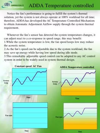
International Journal of Trend in Scientific Research and Development (IJTSRD) @ www.ijtsrd.com eISSN: 2456-6470 2.Problem Formulation 2.1 Governing Equation The relationship between voltage drop from the temperature sensor & the sensed temperature Temperature (℃) = ???? (100℃/VT) or ????= Temperature (℃) (VT/100℃) 2.2 Circuit Design Fig. 3 3.Result 3.1 The relationship graph between output voltage and temperature is shown in fig. 3. As it can be observed that the nature of the graph is straight line. So, we can conclude that voltage is linearly proportional to temperature. Fig. 1 Result of Output Voltage of LM 35 The major component and their circuit connection are shown in Fig. 1. The programming starts from the point where the analog input is read from the LM 35 and displayed on LCD. After that the displayed temperature is compared with the set point and then according to the program, it operates accordingly. Power source is supplied to Arduino to switch on the system and relay source is powered to control the circuit and regulate the circuit as per the program. DC pump uses direct current from power source to move fluid to desired height. Here pump is used to lift water to the height and distribute to each panel of the cooler. Fig. 4 Graph of Voltage vs Temperature 2.3 As shown in the fig. 2, the system is an assembly of a 9 V DC pump and 12 V DC motor, which are connected to the relay unit. Further this relay unit and a 16*2 LCD is connected to the Arduino and power is supplied to the Arduino and relay unit. Assembly 3.2 Comparison between Automatic Temperature Controlled Air Cooler and a Normal Air Cooler on the basis of Power Consumption When Automatic Temperature Controlled Air Cooler is compared with a Normal Air Cooler, it is more cost efficient as the former works only when required whereas latter works continuously even when it is not required. Following are the observations that verifies the above statement. The observation was carried out for period of 80 minutes. DC Motor Rating 12 V, 1.2 A Power 14.4 W Set points are Temperature > 32℃ , motor will be ON Temperature > 34℃ , motor and pump, both will be ON Observations of A Normal Air Cooler: Total Power Consumed = Power of Motor + Power of Pump DC Pump 2.5 - 6 V 1.32 W =14.4 + 1.32 =15.72 W For a period of 80 minutes Total Power Consumed per hour = 15.72 * 60 * 80 =75456 J Fig. 2 @ IJTSRD | Unique Paper ID - IJTSRD23327 | Volume – 3 | Issue – 3 | Mar-Apr 2019 Page: 1335
International Journal of Trend in Scientific Research and Development (IJTSRD) @ www.ijtsrd.com eISSN: 2456-6470 Observations of Automatic Temperature Controlled Air Cooler: According to our observations in 80 minutes period, Motor and Pump, both were OFF for 65 minutes Motor was ON for 15 minutes Pump was not switched ON as temperature didn’t exceeded the set point. Hence, Total Power Consumed = (65*4.32) + (15*18.72) =561.6 J/min Total Power Consumed per hour = 561.6 * 60 5.References [1]Ahmad Faris Bin Zulkifli, A Project on Automatic Room Temperature Control with Security System, University of Malaysia (May 2009) [2]American Society of Mechanical Engineers (ASME), http://www.asme.org [3]Cytron Technologies: Temperature Control System [4]Automatic Temperature Control System using RZK, Zilog Technologies and Zilog Developer Studio, http://www.zilog.com =33696 J [5]Norhaslinda Temperature Control using a Programmable Logic Controller (PLC), University of Technology, Malaysia (November 2008) Binti Hasim, Water Level and 4.Conclusion In this research work, it was observed that the Automatic Temperature Controlled Air Cooler is cost efficient as compared to the conventional air cooler. The automatic cooler operates only whenever required while the conventional air cooler operates continuously even when there is no need. This automatic cooler minimizes the human intervention to the optimum level in comparison with the normal air cooler. [6]https://www.instructables.com/id/Automated -FARM- Arduino-fanlightswater-Pump/ @ IJTSRD | Unique Paper ID - IJTSRD23327 | Volume – 3 | Issue – 3 | Mar-Apr 2019 Page: 1336