Download
1 / 9
90 likes | 107 Views
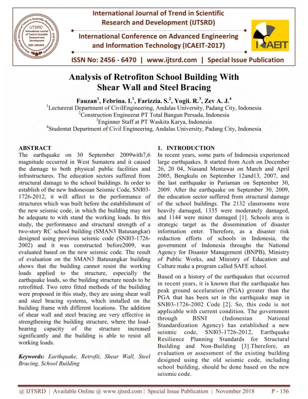
The earthquake on 30 September 2009with7,6 magnitude occurred in West Sumatera and it caused the damage to both physical public facilities and infrastructures. The education sectors suffered from structural damage to the school buildings. In order to establish of the new Indonesian Seismic Code, SNI03 1726 2012, it will affect to the performance of structures which was built before the establishment of the new seismic code, in which the building may not be adequate to with stand the working loads. In this study, the performance and structural strength of a two story RC school building SMAN3 Batusangkar designed using previous seismic code SNI03 1726 2002 and it was constructed before2009, was evaluated based on the new seismic code. The result of evaluation on the SMAN3 Batusangkar building shows that the building cannot resist the working loads applied to the structure, especially the earthquake loads, so the building structure needs to be retrofitted. Two retro fitted methods of the builiding were proposed in this study, they are using shear wall and steel bracing systems, which installed on the building frame with different locations. The addition of shear wall and steel bracing are very effective in strengthening the building structure, where the load bearing capacity of the structure increased significantly and the building is able to resist all working loads. Fauzan | Febrina. I. | Farizzia. S. | Yogii. R. | Zev A. J. "Analysis of Retrofiton School Building With Shear Wall and Steel Bracing" Published in International Journal of Trend in Scientific Research and Development (ijtsrd), ISSN: 2456-6470, Special Issue | International Conference on Advanced Engineering and Information Technology , November 2018, URL: https://www.ijtsrd.com/papers/ijtsrd19128.pdf Paper URL: https://www.ijtsrd.com/engineering/civil-engineering/19128/analysis-of-retrofiton-school-building-with-shear-wall-and-steel-bracing/fauzan<br>

E N D
International Journal of Trend in Scientific Research and Development (IJTSRD) International Conference on Advanced Engineering and Information Technology (ICAEIT-2017) Retrofiton School Building With Shear Wall and SteelBracing International Journal of Trend in Scientific Research and Development (IJTSRD) International Conference on Advanced Engineering and Information Technology (ICAEIT ISSN No: 2456 - 6470 | www.ijtsrd.com | Special Issue Publication International Conference on Advanced Engineering ISSN No: 2456 Special Issue Publication Analysis of Retrofiton Shear Fauzan1, Febrina. 1Lecturerat Department of CivilEngineering, 2Construction Engineerat 3Enginner 4Studentat Department of Civil With Febrina. I.1, Farizzia. S.2, Yogii. R.3, Zev A. J.4 CivilEngineering, Andalas University, Padang City, Engineerat PT Total Bangun Persada, Indonesia Enginner Staff at PT Waskita Karya, Indonesia Civil Engineering, Andalas University, Padang City, 4 City,Indonesia City, Indonesia ABSTRACT The earthquake on 30 September 2009with7,6 magnitude occurred in West Sumatera and it caused the damage to both physical public facilities and infrastructures. The education sectors suffered from structural damage to the school buildings. In order to establish of the new Indonesian Seismic Code, S 1726-2012, it will affect to the performance of structures which was built before the establishment of the new seismic code, in which the building may not be adequate to with stand the working loads. study, the performance and structural stren two-story RC school building (SMAN3 Batusangkar) designed using previous seismic code (SNI03 2002) and it was constructed before2009, was evaluated based on the new seismic code. of evaluation on the SMAN3 Batusangkar shows that the building cannot resist the working loads applied to the structure, especially the earthquake loads, so the building structure needs to be retrofitted. Two retro fitted methods of the were proposed in this study, they are using shear wa and steel bracing systems, which installed building frame with different locations. The addition of shear wall and steel bracing are very effective in strengthening the building structure, where the load bearing capacity of the significantly and the building is able to working loads. Keywords: Earthquake, Retrofit, Shear Wall, Steel Bracing, School Building 1.INTRODUCTION In recent years, some parts o large earthquakes. It started fr 26, 20 04, Niasand Mentawai 2005, Bengkulu on Septemb the last earthquake in Pariam 2009. After the earthquake o the education sector suffered of the school buildings. The heavily damaged, 1335 were and 1144 were minor damag strategic target as the diss information enter. Therefore reduction efforts of schoo government of Indonesia t Agency for Disaster Managem of Public Works, and Mini Culture make a program called SAFE Based on a history of the earthquakes in recent years, it is known t peak ground accelaration (P PGA that has been set in t SNI03-1726-2002 Code [2] applicable with current cond through BSNI Standardization Agency) h seismic code, SNI03-172 Resilience Planning Stan Building and Non-Buildin evaluation or assessment of designed using the old sei school building, should be d seismic code. The earthquake on 30 September 2009with7,6 magnitude occurred in West Sumatera and it caused both physical public facilities and education sectors suffered from to the school buildings. In order to establish of the new Indonesian Seismic Code, SNI03- f Indonesia experienced from Aceh on December ai on March and April ber 12and13, 2007, and man on September 30, on September 30, 2009, ed from structural damage e 2132 classrooms were e moderately damaged, ged [1]. Schools area is ssemination of disaster ore, as a disaster risk ools in Indonesia, the throughs the National ment (BNPB), Ministry istry of Education and alled SAFE school. the performance of structures which was built before the establishment of the new seismic code, in which the building may not adequate to with stand the working loads. In this performance and structural strength of a school building (SMAN3 Batusangkar) designed using previous seismic code (SNI03-1726- before2009, was evaluated based on the new seismic code. The result SMAN3 Batusangkar building s that the building cannot resist the working especially the d on a history of the earthquakes that occurred that the earthquake has PGA) greater than the the earthquake map in ]. So, this code is not ndition. The government donesian has established a new 26-2012, ndards for Structural ng [3].Therefore, an f the existing building eismic code, including done based on the new loads, so the building structure needs to be of the builiding in this study, they are using shear wall which installed on the frame with different locations. The addition of shear wall and steel bracing are very effective in strengthening the building structure, where the load- bearing capacity of the the building is able to resist all (Ind National structure structure increased Earthquake Earthquake, Retrofit, Shear Wall, Steel @ IJTSRD | Available Online @ www.ijtsrd.com | Special Issue Publication | November 2018 Available Online @ www.ijtsrd.com | Special Issue Publication | November 2018 Available Online @ www.ijtsrd.com | Special Issue Publication | November 2018 P - 156
International Journal of Trend in Scientific Research and Development (IJTSRD) | ISSN: 2456-647 2.Evaluation of the existing building In this study, the performance and structural strength of a school public building in West Sumatera, Senior High School (SMAN) 3 Batusangkar Building, was evaluated. The school was two-story RC building, which is designed using previous seismic code (SNI 03-1726-2002) and constructed before2009, so it is necessary to evaluate based on the new seismic code. The details of building are described in the Figure1and Table1. Table1:DetailsoftheSMAN3 Batusangkar building Structural Elements Properties B1(30cm x65cm) B2(25cm x40cm) B3(25cm x30cm) B4(30cm x40cm) K1(30cm x40cm) K2(30cm x30cm) 12 cm 7.2 m 56 K-225 (fc'=18.675MPa) Figure2. Response spectrum graph for Batusangkar CitybasedonSNI1732-2012 Calculation and structural analysis are applied by a three-dimensional structure made of a computer program, ETABS 9.7.1[4]. The loads a retaken into account included the dead load/weigh to fits own building, live, and seismic load. An analysis of the seismic load used dynamic analysis based on SNI03- 1726-2012Code. The minimum load for design of buildings and other structures code, SNI 1727-2013 Code, was used to calculate the working loads [5].The dynamic analysis used seismic response spectrum design for Batusangkar City, as seen in the Figure2 (source: http://puskim.pu.go.id, application design spectraofIndonesia2011)[6]. 2.1.The flexural capacity of existing columns Figure3 shows the P-Minter action diagram for columns of the building structure. It can be seen in the figure, there are several points of axial forces and bending moments exceed the inter action diagram, this means that the capacity of column is not strong enough to resist the working loads Beam size Column size Slab thickness Total height of frame Number of column Compressive strength of concrete Yield strength of reinforcement (fy) Plan area 320MPa 52.5mx10m Figure1. Perspective and plan of the school building @ IJTSRD | Available Online @ www.ijtsrd.com | Special Issue Publication | November 2018 P - 157
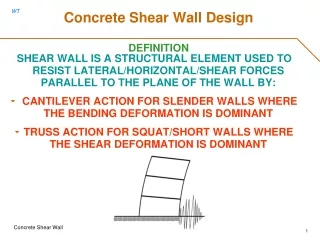
International Journal of Trend in Scientific Research and Development (IJTSRD) | ISSN: 2456-647 Based on the above analysis result of the existing building by using the new Indonesian seismic code, it can be said that the SMAN 3 Batusangkar building structure is not capable to resist the working loads. 3. Recommendation of the retrofitting 3.1. Retrofitting of structures Retrofitting is a method to increase the resistant capacity of structure. A seismic retrofit provides existing structures with more resistance to seismic activity due to earthquakes. Retrofitting techniques can be classified as local and global retrofitting. Local retrofitting is the maintenance of local deficiencies in building like crushing of columns, flexure and shear failure of beams, columns and shear walls, also rebuilding infill masonry. Global retrofitting is maintenance of global deficiencies in building like plan and vertical irregularities. The global retrofit includes the addition of shear wall and steel bracing [7]. In this study, there are two retrofitted systems, shear wall and steel bracing systems which was analysed. The systems were attached on the building frames with different locations. 3.1.1. Retrofitted with shear wall Shear wall system is one of the most commonly used lateral- load resisting systems in multi-story buildings. Shear wall has very high in-plane stiffness and strength which can be used to simultaneously resist large horizontal loads and support gravity loads [8]. The proposed thickness of shear wall is 25 cm with compressive strength of concrete (fc’) is 25 Mpa. The yield strengh of the D-16 mm logitudinal reinforcement is 390 MPa. The yield strengh of the D-10 mm transversal reinforcement is 240 MPa. Specification detail of the shear wall in the retrofitted structure can be seen in the Figure 4. Figure3. Interaction diagram of the existing column 2.2. The shear capacity of existing columns Table 2: Column shear capacity of the existing structure Column Vu,ETA BS (kn) K130/40(1st Floor) 67,15 K230/30(1st Floor) 71,25 K230/30(2nd Floor) 60,4 Table 2 shows the shear capacity of the columns. All columns have a ten mm diameter with a 200 mm space between two shear reinforce met. As seen in the table, the shear capacity of column K1 is sufficient, nominal shear is higher than the ultimate shear (Vu). However, the shear capacity of both columns K2 (1st and 2nd floors) could not meet the requirement. 2.3. Inter Story Drift (SNI03-1726-2012Code) Table3: Inter story drift of the existing structure Sto ry (mm) (mm) 2 3.6 5.43 1 3.6 7.75 StoryDisp. (mm) (mm) 1 10.93 10.93 2 24.1 13.17 Table 3 shows the value of inter story drift in x and y- directions. From the table, it can be seen that maximum of the story drift for x and y-direction are 0.3032 m and 0.04167 m, respectively. These values are less than the allowable inter story drift of 0.04154 m. φVn (kn) 103,99 OK 55,71 55,71 Exp.(Vu ≤φ Vn) NOTOK NOTOK Disp. DriftX Δs Δa (mm) Δs≤ Δa (mm) 19.910 51.346 OK 28.417 51.923 OK DriftY Δs (mm) 40.08 51.346 OK 48.29 51.923 OK Δa (mm) Δs≤ Δa Figure4. Specification detail of shear wall @ IJTSRD | Available Online @ www.ijtsrd.com | Special Issue Publication | November 2018 P - 158
International Journal of Trend in Scientific Research and Development (IJTSRD) | ISSN: 2456-647 Model G, the bracing attached in X and Y directions (U shape) on 1st and 2nd floors (Figure 6g) Model H, the bracing attached in Y direction and central part of the building in X direction on 1stand 2nd floors (Figure 6h) Four different locations that added to the shear wall system on the building were modelled, as shown in Figure 6: Model A, shear wall attached on a core area of stairs in the1st floor (Figure 6a) Model B, shear wall attached on a core area of stairs in the1st and 2nd floors (Figure 6b) Model C, shear wall attached on a corner area of the building in the1st floor (Figure 6c) Model D, shear wall attached on a corner area of the building in the1st and 2nd floors (Figure 6d) 3.1.2. Retrofitted with steel bracing Bracing system is one of structural system which forms an integral part of the frame. Bracing is efficient because the diagonals work in axial stress and therefore it is called for minimum member sizes in providing the stiffness and strength against horizontal shear [9]. In this study, steel bracing with the V-inverted was selected to retrofit the existing structure. Based on the results of bracing designed calculations (with input parameters: yield strength of 390 MPa, ultimate strength of 520 MPa and elastic modulus of 200.000 MPa), IWF profile with dimension of 250.250.9.14 provides enough lateral stiffness and stability. The specification detail of the steel bracing can be seen in Figure 5. (a)ModelA (b)ModelB Figure5. Specification detail of steel bracing Four different locations that added to the steel bracing system on the building were modelled, as shown in Figure 6: Model E, the bracing attached on X direction both front and rear on 1st floor (Figure 6e) Model F, the bracing attached in corners area X and Y directions (L shape) on 1st floor and 2nd floors (Figure 6f) (c)Model C @ IJTSRD | Available Online @ www.ijtsrd.com | Special Issue Publication | November 2018 P - 159
International Journal of Trend in Scientific Research and Development (IJTSRD) | ISSN: 2456-647 (g) Model G (d)Model D (h) Model H (e) Model E Figure6. The 3-D modeling of retrofitted structures 3.2. Analysis of retrofitted structures Structural analysis using ETABS v9.7.1 was carried out for all models. From the eight retrofitted building models analyzed, the result of inter story drift shows that the four models (Models A,C,E, and H) do not meet requirement based on new seismic code, SNI 1726-2012, where the story drift exceeds the allowable drift, as shown in Table 4. Therefore, there are four models recommended for retrofitting structures: models B and D using shear wall system and models F and G using steel bracing system. The comparison for recommanded models of the retrofitted building are discussed below. (f) Model F @ IJTSRD | Available Online @ www.ijtsrd.com | Special Issue Publication | November 2018 P - 160
International Journal of Trend in Scientific Research and Development (IJTSRD) | ISSN: 2456-647 Table4: Inter story drift of all retro fitted models Drift X (mm) (mm) (mm) 0.0255 0.0850 0.054 NOT 0.0217 0.0024 0.0080 0.054 OK 0.0059 0.0197 0.054 OK 0.0022 0.0073 0.054 OK 0.0225 0.0750 0.054 NOT 0.0164 0.0009 0.0030 0.054 OK 0.0141 0.047 0.054 OK 0.0008 0.0027 0.054 OK 0.023 0.0767 0.054 NOT 0.021 0.0002 0.0007 0.054 OK 0.016 0.0533 0.054 OK 0.0001 0.0000 0.054 OK 0.0162 0.054 0.054 OK 0.0001 0.0000 0.054 NOT 0.0021 0.0238 0.0793 0.054 OK 0.0022 0.0073 0.054 OK Disp. X(mm) 0.0279 0.0024 0.0081 0.0022 0.0234 0.0009 0.0149 0.0008 0.0232 0.0002 0.016 0.0001 0.0162 0.0001 0.026 0.0022 Δs Δa Disp.Y (mm) Drift.Y (mm) 0.014 0.0079 0.012 0.0066 0.012 0.0009 0.012 0.0046 0.012 0.0089 0.0095 0.0021 0.0098 0.0021 0.0138 0.0076 Δs Δa (mm) Mo del A Sto ry 2 1 2 1 2 1 2 1 2 1 2 1 2 1 2 1 Δs≤ Δa Δs≤ Δa (mm) 0.0450 0.054 OK 0.0263 0.054 OK 0.0387 0.054 OK 0.022 0.054 OK 0.0397 0.054 OK 0.015 0.054 OK 0.041 0.054 OK 0.0153 0.054 OK 0.04 0.054 OK 0.0297 0.054 OK 0.0317 0.054 OK 0.007 0.054 OK 0.0327 0.054 OK 0.007 0.054 OK 0.046 0.054 OK 0.0253 0.054 OK 0.0079 0.0182 0.0066 B C 0.0045 0.0169 0.0046 D E 0.0089 0.012 0.0021 0.012 F G H 0.021 0.0076 3.3. Table 5: Comparison of shear force in the beam between existing and retrofitted structures Shear Force (kg) Bea m ry Int. 1 2068 4 2 2 3337 2553 1906 1867 1791 Ext. 1 6649 4298 3152 3560 4025 2 376 248 The location point of columns and beams to compared the structural responses The location point of columns and beams to compare structural response can be seen in Figure 7. The positions are taken from one interior beam and another one interior column of the center of each floor. Sto Exist B D F G 1773 1474 6 1542 3 1561 5 248 219 242 Table 6: Comparison of bending moment in the beam between existing and retrofitted structures Bending Moment (kg) Bea m ry t Int. 1 1901 8 6 2 5347 2469 1409 1199 1121 Ext. 1 5092 3822 2815 3421 3797 2 258 131 Sto Exis B D F G Figure 7. Location point of columns and beams to compare the structural response 4. Results and discussion 4.1. The Internal Force in Beams The comparison of shear force on the beam between Existing and retrofitted building is shown in Table5. From the table, it can be seen that the building using steel bracing and shear wall have smaller value than the existing structure. The retrofitting provides great rigidity to the structure, so it reduces the shear force in the structure by a round 90%.Table 6 shows a comparison of bending moment on the beam. As seen in the table, the bending moment of the beam was also reduced upto70%duetothepresent of shear wall and steel bracing in the building. 1722 1404 6 1577 3 1622 3 127 119 125 4.2. The comparison of internal force in the columns (axial, shear, and bending moment) between exsisting and retrofitted buildings can be seen in Tables 7, 8, and9, respectively. It can be seen from Table 7, the axial force on Models B and D were lower around 20 – 35% than existing building, however, on Models F and G, were higher around 32 – 35% than existing building. From Table 8, shear force in the retrofitted The Internal Force in Columns @ IJTSRD | Available Online @ www.ijtsrd.com | Special Issue Publication | November 2018 P - 161
International Journal of Trend in Scientific Research and Development (IJTSRD) | ISSN: 2456-647 structures were smaller than the existing structure. The percentage of reduction that occurs in the shear force of the columns are around 90 – 95%. This is mainly due to the retrofit can resist the lateral loads, especially the earth quaked load. Adding the shear wall and steel bracing systems on the building structure can reduce bending moment. The percentage of bending moment reduction around 95% compared to the existing structure, as seen in the Table 9. Table 7: Comparison of axial force in the columns between the existing and the retrofitted structures Axial Force (kN) Col. Story Exist B Int 1 76,6 29,89 16,53 121,8 123,63 2 24,86 10,97 Ext. 1 61,16 4,37 57,16 64,62 2 17,55 0,89 Table 8: Comparison of shear force in the columns between the existing and the retrofitted structures Shear Force (kN) Col. Story Exist B Int 1 68,91 2,77 2 22,09 9,83 Ext. 1 77,53 24,71 3,26 14,62 14,93 Col. 2 6,83 6,18 Table 9: Comparison of bending moment in the columns between the existing and the retrofitted structures Bending Moment (kNm) Col Story Exist B Int. 1 134,86 8,44 2 38,78 19,28 17,57 0,87 Ext. 1 145,25 28,1 2 40,47 38,8 4.3. Displacements Comparison of X and Y direction displacements in interior and exterior columns between exsisting and retrofitted structures can be seen in Figures 8 and 9. As seen in the figures, the displacement of the exterior column in x and y direction in retrofitted structure was reduced around 99% of the existing structure. D F G 6,22 9,46 8,61 64,87 12,15 0,56 12,14 Figure8. Comparison of X-dir. displacement between existing and retrofitted structures D F G 0,68 0,61 8,65 0,51 0,73 0,6 0,74 3,16 3,52 D F G 4,22 3,27 4,04 1,04 1,79 22,07 20,26 20,21 17,61 17,65 Figure9. Comparison of Y-dir. displacement between existing and retrofitted structures @ IJTSRD | Available Online @ www.ijtsrd.com | Special Issue Publication | November 2018 P - 162
International Journal of Trend in Scientific Research and Development (IJTSRD) | ISSN: 2456-647 4.4. Interaction diagram of the columns after retrofitting Figure 10 shows the P-M interaction diagram of column on the four models of retrofitted building structures. From the figure, it can be seen that the axial forces and bending moments for all models are not exceeded the interaction diagram, that means the capacity of column is strong enough to resist the working loads (b) Model D (a)Model B (b) (c) Model F @ IJTSRD | Available Online @ www.ijtsrd.com | Special Issue Publication | November 2018 P - 163
International Journal of Trend in Scientific Research and Development (IJTSRD) | ISSN: 2456-647 school building to reduce the internal force and displacement due to the working loads. Retrofitted using steel bracing system is more economical and easier to be installed than the shear wall, so the method of retrofit using steel bracing models F recommended for strengthening the structure of SMA N 3 Batusangkar, which it can also be applied to other typical school buildings. 4. and G are very 5. 1.Disaster of Management Coordination Board of West Sumatra, (2009), The Map of Total Damage Public Facilities caused Earthquake in West Sumatra, Indonesia. (d) Model G REFERENCES 4.5. Table 10 shows the comparison of the cost of retrofitted building for the four retrofitted building models which analyzed by Unit Price of Work of Batusangkar City, 2017 [10]. The table shows that the use of shear wall has cost minimum Rp. 253.044.039,- (Model B), whereas the use of steel bracing required lower cost, particularly of Model F, which amounted Rp. 192.125.000,-. Table 10: Comparison of the retrofit structure cost Retrofit Method (1) (2) per Volume Cost and volume of the work 2.National Standardization Agency of Indonesia, (2002), Design Standard of Earthquake Resistance for Buildings, SNI 03-1726-2002, Jakarta, Indonesia. 3.National Standardization Agency of Indonesia, (2012), Design Method of Earthquake Resistance for Buildings and Other Structures, SNI 1726- 2012, Jakarta, Indonesia. Volume Unit Price Cost of Material (4) = 2 x 3 253.044.039 4.Computers and Structures, Inc., (2005), Manual ETABS (Integrated Building Design Software). California, USA. (3) Model B(SW) Model D(SW) Model F(SB) Model G(SB) 5.CONCLUSION From the above structural analysis, it can be concluded that: 1. The building of SMA N 3 Batusangkar is unable to resist the working loads based on the evaluation of the feasibility structure which analyzed using SNI 1726-2012. The structure should be retro fitted. 2. Retrofitted of the building by adding steel bracing and shear wall systems are very effective for reducing the displacement by 60- 99% and the internal force by 10-95% compared to the existing structure. 3. Models B and D which used shear wall system, and models F and G used steel bracing system can be applied in the retrofitted 39,6 m3 Rp. 6.390.000 Rp. 6.390.000 Rp. 12.500 5.National Standardization Agency of Indonesia, (2003), Minimum load for the design of buildings and other structures, Jakarta, Indonesia. 50,4 m3 322.056.050 15370 kg 17291 kg 192.125.000 6.http://puskim.pu.go.id/Aplikasi/desain_spektra_ indonesia_2011/ Rp. 12.500 216.140.000 7.Central Public Works Department and Indian Building Congress, (2007), Handbook on Seismic Retrofit of Buildings. Association Indian Institute Technology. 8.S., Anshuman, et al., (2011), Solution of Shear Wall Location in Multi-Story Building. IJSCE vol. 2 no. Civil Engineering Group, BITS Pilani, India. 9.M., Adhitya, et al., (2015), Study on Effective Bracing Systems for High Rise Steel Structures. SSRG-IJCE vol. 2 issue 2. Civil Engineering East West Institute of Technology, Bangalore-91, India. 10.Central Public Works Department of Batusangkar City, (2017), Work Unit Price Triwulan I 2017, Indonesia. @ IJTSRD | Available Online @ www.ijtsrd.com | Special Issue Publication | November 2018 P - 164