Download
1 / 5
50 likes | 55 Views
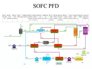
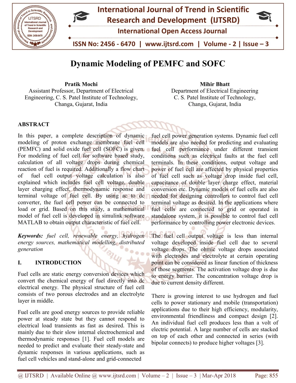
In this paper, a complete description of dynamic modeling of proton exchange membrane fuel cell PEMFC and solid oxide fuel cell SOFC is given. For modeling of fuel cell for software based study, calculation of all voltage drops during chemical reaction of fuel is required. Additionally a flow chart of fuel cell output voltage calculation is also explained which includes fuel cell voltage, double layer charging effect, thermodynamic response and terminal voltage of fuel cell. By using ac to dc converter, the fuel cell power can be connected to load or grid. Based on this study, a mathematical model of fuel cell is developed in simulink software MATLAB to obtain output characteristic of fuel cell. Pratik Mochi | Mihir Bhatt "Dynamic Modeling of PEMFC and SOFC" Published in International Journal of Trend in Scientific Research and Development (ijtsrd), ISSN: 2456-6470, Volume-2 | Issue-3 , April 2018, URL: https://www.ijtsrd.com/papers/ijtsrd11087.pdf Paper URL: http://www.ijtsrd.com/engineering/electrical-engineering/11087/dynamic-modeling-of-pemfc-and-sofc/pratik-mochi<br>

E N D
International Research Research and Development (IJTSRD) International Open Access Journal Dynamic Modeling of PEMFC and SOFC Dynamic Modeling of PEMFC and SOFC International Journal of Trend in Scientific Scientific (IJTSRD) International Open Access Journal ISSN No: 2456 ISSN No: 2456 - 6470 | www.ijtsrd.com | Volume 6470 | www.ijtsrd.com | Volume - 2 | Issue – 3 Dynamic Modeling of PEMFC and SOFC Pratik Mochi Department of Electrical C. S. Patel Institute of Technology, Mihir Bhatt Bhatt Assistant Professor, Department of Electrical Engineering, C. S. Patel Institute of Technology, Changa, Gujarat, India Department of Electrical Engineering C. S. Patel Institute of Technology, Department of Electrical Engineering C. S. Patel Institute of Technology, Changa, Gujarat, Gujarat, India fuel cell power generation systems. Dynamic fuel cell models are also needed for predicting and evaluating fuel cell performance under different transient conditions such as electrical faults at the fuel cell terminals. In these conditions, output voltage and power of fuel cell are affected by physical properties of fuel cell such as voltage drop inside fuel cell, capacitance of double layer charge effect, material conversion etc. Dynamic models of fuel cells are also needed for designing controllers to control fuel cell terminal voltage as desired. In the applications where fuel cells are connected to grid or operated i standalone system, it is possible to control fuel cell performance by controlling power electronic devices. The fuel cell output voltage is less than internal voltage developed inside fuel cell due to several voltage drops. The ohmic voltage drops asso with electrodes and electrolyte at certain operating point can be considered as linear function of thickness of those segments. The activation voltage drop is due to energy barrier. The concentration voltage drop is due to current density different. There is growing interest to use hydrogen and fuel cells to power stationary and mobile (transportation) applications due to their high efficiency, modularity, environmental friendliness and compact design [2]. An individual fuel cell produces less than electric potential. A large number of cells are stacked on top of each other and connected in series (with bipolar connects) to produce higher voltages [3]. ABSTRACT In this paper, a complete description of dynamic modeling of proton exchange membrane fuel (PEMFC) and solid oxide fuel cell (SOFC) is given. For modeling of fuel cell for software based study, calculation of all voltage drops during chemical reaction of fuel is required. Additionally a flow chart of fuel cell output voltage calculation i explained which includes fuel cell voltage, double layer charging effect, thermodynamic response and terminal voltage of fuel cell. By using ac to dc converter, the fuel cell power can be connected to load or grid. Based on this study, a mathematica model of fuel cell is developed in simulink software MATLAB to obtain output characteristic of fuel cell. Keywords: fuel cell, renewable energy, energy sources, mathematical modelling, distributed generation I. INTRODUCTION In this paper, a complete description of dynamic modeling of proton exchange membrane fuel cell (PEMFC) and solid oxide fuel cell (SOFC) is given. For modeling of fuel cell for software based study, calculation of all voltage drops during chemical reaction of fuel is required. Additionally a flow chart of fuel cell output voltage calculation is also explained which includes fuel cell voltage, double layer charging effect, thermodynamic response and terminal voltage of fuel cell. By using ac to dc converter, the fuel cell power can be connected to load or grid. Based on this study, a mathematical model of fuel cell is developed in simulink software MATLAB to obtain output characteristic of fuel cell. fuel cell power generation systems. Dynamic fuel cell models are also needed for predicting and evaluating performance under different transient conditions such as electrical faults at the fuel cell terminals. In these conditions, output voltage and power of fuel cell are affected by physical properties of fuel cell such as voltage drop inside fuel cell, itance of double layer charge effect, material conversion etc. Dynamic models of fuel cells are also needed for designing controllers to control fuel cell terminal voltage as desired. In the applications where fuel cells are connected to grid or operated in standalone system, it is possible to control fuel cell performance by controlling power electronic devices. fuel cell, renewable energy, hydrogen energy sources, mathematical modelling, distributed The fuel cell output voltage is less than internal voltage developed inside fuel cell due to several voltage drops. The ohmic voltage drops associated with electrodes and electrolyte at certain operating point can be considered as linear function of thickness of those segments. The activation voltage drop is due to energy barrier. The concentration voltage drop is due to current density different. Fuel cells are static energy conversion devices which convert the chemical energy of fuel directly into dc electrical energy. The physical structure of fuel cell consists of two porous electrodes and an electrolyte layer in middle. energy conversion devices which convert the chemical energy of fuel directly into dc electrical energy. The physical structure of fuel cell consists of two porous electrodes and an electrolyte There is growing interest to use hydrogen and fuel cells to power stationary and mobile (transportation) applications due to their high efficiency, modularity, environmental friendliness and compact design [2]. An individual fuel cell produces less than a volt of electric potential. A large number of cells are stacked on top of each other and connected in series (with bipolar connects) to produce higher voltages [3]. Fuel cells are good energy sources to provide power at steady state but they cannot respond to electrical load transients as fast as desired. This is mainly due to their slow internal electrochemical and thermodynamic responses [1]. Fuel cell models are needed to predict and evaluate their steady dynamic responses in various applications, such as fuel cell vehicles and stand-alone and grid Fuel cells are good energy sources to provide reliable power at steady state but they cannot respond to electrical load transients as fast as desired. This is mainly due to their slow internal electrochemical and Fuel cell models are evaluate their steady-state and dynamic responses in various applications, such as and grid-connected @ IJTSRD | Available Online @ www.ijtsrd.com @ IJTSRD | Available Online @ www.ijtsrd.com | Volume – 2 | Issue – 3 | Mar-Apr 2018 Apr 2018 Page: 855
International Journal of Trend in Scientific Research and Development (IJTSRD) ISSN: 2456-6470 C.Concentration voltage drop: This voltage drop depends on current density. At higher current density, the reaction of chemicals becomes slow and it is due to concentration voltage drop. The equation of this voltage drop is given as, ?????= ?? ?????1 − ? Where, z = numbers of electrons Ilim= fuel cell limit current D.Double layer charge effect: As the electrons flow from cathode to anode through external load, the electrodes act ac two layers of capacitor having the charge and the membrane between both acts as dielectric between both electrodes forming a capacitor. ?? = ?1 − ? ×??? ???(???? + ?????) By considering all these voltage drops and double layer charge effect, the output voltage is given by, ???? = ? − ???? − ?? − ??ℎ? III. Dynamic modeling of SOFC An SOFC based Distributed generation System is normally interfaced with the utility network through a set of power electronics devices. The interface is very important as it affects the operation of the fuel cell system and the power grid. Various control schemes haven proposed in the recent work to interface different energy sources to utility grid. Nernst equation to give output voltage of Solid Oxide fuel cell is given by, 4?ln [???? Where E0,cell is temperature dependent term. Similar to PEMFC output voltage, same equation of Vcell is used to calculate actual voltage generated in fuel cell i.e. it also includes activation, concentration and ohmic voltage drops. A.Activation voltage drop: This voltage drop is due to activation of energy barrier when there is a chemical reaction inside a fuel cell at lower currents. The activation voltage drop for SOFC can be estimated by following equation. ???? = ?? II. Dynamic modeling of PEMFC The output voltage of PEMFC is given by Nernst equation ????? = ??,???? + ?? 2??? [???(???)?.?] Where, Ecell = Potential of each cell Eo,cell = Reference potential F = Faraday’s constant R = Gas constant T = Fuel cell temperature PH2 = Pressure of hydrogen PO2 = Pressure of oxygen. The overall effect of the fuel and oxidant delay is represented by a voltage ? ?????? ? ?] Ed,cell.= ?[?(?)− ?(?)¤? Where, ¤ is convolution operator and et/τ is time lag function. So total voltage generated is given by, ?????= ??.????+?? 2???[???(???)?.?] − ??,???? Under normal operating condition, the fuel cell output voltage is less than voltage generated due to ohmic voltage drop, activation concentration voltage drop. ?????= ?????− ????− ????− ????? And Vout = Ncell x Vcell Where Ncell is number of fuel cell stack A.Activation voltage drop: The activation voltage drop is a function of the PEMFC current and temperature. Vact can be described as sum of Vact1 and Vact2[1]. Vact = Vact1 + Vact2 Vact = [ηo + (T-298)*a] + [T*b*ln(i)] Where,ηo,a and b are empirical constants. Vact1 is the voltage affected only by the fuel cell internal temperature and Vact2 is both current and temperature dependent.The equivalent resistance of activation voltage drop is ratio of Vact2 and fuel cell current. Ract = Vact2/I. B.Ohmic voltage drop: The ohmic resistance of PEMFC consists of resistance of polymer membrane and resistance of electrodes. Vohm = Vmemb + Vele voltage drop and ???? ??? ?? ?] ????? = ??,????+?? ??? ????? ????? (? ?0) This equation is called Tafel equation in which the value of voltage drop approaches infinite if current is zero which is undesirable. The significance of R, T, z @ IJTSRD | Available Online @ www.ijtsrd.com | Volume – 2 | Issue – 3 | Mar-Apr 2018 Page: 856
International Journal of Trend in Scientific Research and Development (IJTSRD) ISSN: 2456-6470 and F is same as in PEMFC. The value of β is 0.5 for solid oxidefuel cell [5]. B.Ohmic voltage drop: The resistances due to electrodes, electrolyte and interconnection of several fuel cells are responsible for total Ohmic voltage drop ??ℎ? = ?????????? + ???????????? + ???????????????? C.Concentration voltage drop: For higher current densities and due to slow diffusion process, the reactants cannot be transported to reaction site as fast as needed and this causes a significant voltage drop called Concentration voltage drop. This voltage drop can be obtained by calculation voltage drops at cathode and anode terminals. ????? = ?? (???? D.Double layer charge effect: Similar to PEMFC, a double layer charge effect is present in SOFC in same manner and can be estimated by same equation as in PEMFC. The difference is that, in SOFC, the electrodes are porous and it makes the value of capacitance to be higher comparatively. After considering the voltage drops and capacitor effect, the output voltage of SOFC can be calculated as below. ???? = ????? − ???? − ????? − ??ℎ? − ?? IV. Flow chart of fuel cells output voltage calculation For the mathematical modeling of fuel cell, a step by step approach in a form of flow chart is shown below. This includes input parameters and calculation of different voltage drops. As shown in figure, the input parameters of fuel cell are Pressure at anode and cathode terminal (Pa and Pc), room temperature (Troom), Initial temperature (Tinitial), Air temperature (Tair), fuel temperature (Tfuel), hydrogen flow rate (MH2), water vapour flow rate(MH2o). These parameters are applied to Nernst equation to calculate the fuel cell internally generated voltage. Here the material conservation and thermodynamic effect of fuel cell is neglected. So the voltage drops can be calculated as per the equations and voltage drop due to capacitor effect in fuel cell can be calculated. The addition of all calculated voltage drops when subtracted from voltage estimated by Nernst equation, gives terminal voltage of fuel cell. The equations and parameters selected for modelling are important for analysis and control of fuel cell [6]. Fig 1: Flow chart of fuel cell output voltage Calculation V. Simulink model of fuel cells Input Parameters i.ePa , Pc , Troom , Tinitial , Tair , Tfuel , MH2, MH2o Nernst Equation to calculate fuel cell internally generated voltage Calculation of Ohmic voltage drop Calculation of Activation voltage drop Calculation of Concentration voltage ?)???? ? ? ?)???? (???? ? 4?ln?(??? 4?ln?(??? )?? − ?? )?? ? Calculation of voltage drop due to capacitor double layer charge effect Voltage available at the terminal of fuel cell For dynamic modelling of fuel cells, mathematical equations of voltage drops, Nernst equation are modelled in Simulink software MATLAB to get the output voltage. The mathematical model of PEMFC is shown in Fig 2. The standard values of parameters for calculation of Fuel cell output voltage is given below. In this model, the thermodynamic effect of fuel cell is neglected. Table I. PEMFC parameters Value Parameter Gas Constant R Faraday’s Constant F Pressure of anode Pressure of cathode Absolute Temperature Reference Temperature Ilim Number of cells Double layer capacitance Heat transfer coefficient 8.3143 J/mol*K 96485 J 1 Atm 1 Atm 298.16 K 273.15 K 25.1 Amp 24 1 F 10 W/K @ IJTSRD | Available Online @ www.ijtsrd.com | Volume – 2 | Issue – 3 | Mar-Apr 2018 Page: 857
International Journal of Trend in Scientific Research and Development (IJTSRD) ISSN: 2456-6470 Fig 4. Mathematical model of SOFC A mathematical model of SOFC can also be implemented by simulating Nernst equation and voltage drops to obtain output voltage. The parameters considered for calculation are given below. Table II. SOFC parameters Fig 2. Mathematical model of PEMFC Considering above parameters, the model of PEMFC is developed and voltage-current characteristic is shown in fig 3. Parameter Gas Constant R Faraday’s Constant F Ideal standard potential Load Resistance Absolute Temperature Reference Temperature Iinitial Molar Constant H2 Molar Constant O2 Molar Constant H2O Value 8.3143 J/mol*K 96485 J 1.18 V cell 10 Ω 1273 K 273.15 K 100 Amp 8.43 e-4 K mol/(s atm) 2.52 e-4 K mol/(s atm) 2.81 e-4 K mol/(s atm) For this model of SOFC, with above parameters, the output voltage of 1.26V is obtained. The advantage with SOFC is that, as a working temperature is high (600°C – 1000°C) it can be used with combined heat and temperature so as to give higher efficiency. According to the load profile, the feasible fuel cell capacity can be determined, whereas a diesel generator should be operating at the rated power as much as possible [4]. Fig 3. PEMFC V-I Characteristic In V-I characteristic, we can see that the output voltage is going down because of three voltage drops. Initially at lower current values activation and concentration voltage drop is higher and than ohmic drop causes further reduction in output voltage. @ IJTSRD | Available Online @ www.ijtsrd.com | Volume – 2 | Issue – 3 | Mar-Apr 2018 Page: 858
International Journal of Trend in Scientific Research and Development (IJTSRD) ISSN: 2456-6470 VI. CONCLUSION REFERENCES 1.M.HashemNehrir, Caisheng Wang “ Modeling and control of fuel cell distributed generation Application” ISBN 978 0 470 23328 3 IEEE 2009. A software based dynamic modeling of fuel cell can be used to predict its performance for different operating conditions and parameters, by the V-I characteristic. The voltage drop inside the fuel can also be estimated by this model and initiative can be taken to reduce the voltage drop to increase the output voltage and efficiency. The dynamic behavior of PEMFC and SOFC can also be assessed by changing the pressure, temperature or flow rates of fuel and oxidant. 2.Caisheng Wang, Modeling and control of hybrid wind/PV/FC distributed generation systems, PhD thesis, Montana State University, July 2006. 3.N. Prema Kumar, K. NirmalaKumari, K.M.Rosalina, “Modeling Design of Solid Oxide Fuel Cell Power System for Distributed Generation Applications,” International Journal of Advanced Research in Computer Engineering & Technology (IJARCET), Vol. 1, 9 November 2012. ACKNOWLEDGEMENT The authors are grateful to their family members, head of the department, colleagues, referees and the team of management for motivating, guiding and supporting to carry out the research activity for betterment of their career. 4.Abou El-Maaty M. Abd El-Aal, “Modeling and Simulation of a photovoltaic Fuel cell hybrid system”, a dissertation report university of Kassel, April 15, 2005. 5.P.Li and B.Lehman, “A design method for paralleling current mode controlled DC-DC converters”, IEEE Transactions on Power Electronics, 19(3), 748-756, 2004. 6.S. Carvalho, “Accurate Matlab/Simulink model of a Power Generation System Based on Fuel Cells” pp 5357-5364, 978-1-4673-2421-2/12 ©2012 IEEE. @ IJTSRD | Available Online @ www.ijtsrd.com | Volume – 2 | Issue – 3 | Mar-Apr 2018 Page: 859