Doppler
Doppler. Doppler Effect or Shift. is the change in frequency (and wavelength) due to motion of a sound source, receiver, or reflector. is the difference between the received & transmitted frequencies measured in Hertz (Hz).


Doppler
E N D
Presentation Transcript
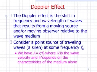
Doppler Effect or Shift is the change in frequency (and wavelength) due to motion of a sound source, receiver, or reflector. • is the difference between the received & transmitted frequencies measured in Hertz (Hz). • is used to determine the velocity of the moving reflectors (Recall: velocity is speed & direction.)
If the source is moving toward the receiver, or if the receiver is moving toward the source, or if the reflector is moving toward the source and receiver, the received wave has a higher frequency than would be experienced without the motion. O X X
A moving source (red blood cells) approaching a stationary receiver (transducer), the cycles are compressed in front of the source as it moves into its own wave.
The source motion shortens the wavelength ahead of it as observed by a stationary receiver in front of the approaching source wavelength = frequency
Conversely, if the source motion is away, the received wave has a lower frequency & wavelength
Only the moving reflector is of interest for diagnostic Doppler ultrasound. The amount of or in the frequency depends on the: • speed of motion • angle between the wave propagation direction& the motion direction • frequency of the source’s wave
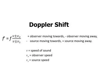
Doppler equation • relates the detected Doppler shift (∆F) to those factors that affect it ∆F = 2 x F0 x V x COS C
∆F = 2 x F0 x V x COS C F0is the central sound frequency (aka - transmitted, emitted, incident, or ongoing frequency) transmitted by the transducer. ∆F and F0are directly related; if F0is doubled, then ∆F is doubled
∆F = 2 x F0 x V x COS C V is the velocity of the moving reflector (red blood cells) ∆F and Vare directly related; if Vis doubled, then ∆F is doubled
∆F = 2 x F0 x V x COS C COS is the cosine of the angle between the direction of blood flow & the axis of the beam (the Doppler angle). If the cosine is doubled,the Doppler shift doubles.
sin & cos (in brief) • A is the starting point (in our case, the blood cell), the side opposite of angle A is called ‘a’ • C is the right angle; the hypotenuse (the side of the triangle opposite of angle C) is called ‘c’ • B is the remaining angle; the side of the triangle opposite angle B is called ‘b’ c a c a c a A C C C
sin A = a/c As A , side ‘a’ also ; eventually ‘a’ will equal ‘c’ As A approaches 90°, ratio a/c becomes closer to 1 When A equals 90°, a/c = 1 sin A = 1 when A = 90° or the sin 90° = 1 a a c c a c A
cos A = b/c As A , side ‘b’ ; eventually side ‘a’ = side ‘c’. As A approaches 90°, the ratio b/c becomes closer to 0. When A equals 90°, b/c = 0, • cos A = 0 when A = 90° (or the cos 90° = 0) c a c a c a A b b b
∆F = 2 x F0 x V x COS C • Cosine values range from 0 to 1. • It is an inverse relationship. As the angle , the cosine . Example cosine of 0° = 1; cosine of 90° = 0
∆F = 2 x F0 x V x COS C C is the speed of sound in the medium. The speed of sound is approximately 1540 m/s or 1.54 mm/s. If the speed of sound in the medium ; the value of the detected Doppler shift . C is inversely related to ∆F
Detection of Doppler Shift Doppler ultrasound systems do notuse the Doppler equation to calculate the Doppler shift. The ultrasound system compares the frequency of the received echo (fr) to the frequency of the transmitted pulse (ft).
Doppler Frequency (fd) =Reflected Frequency (fr) - Transmitted Frequency (ft) When: • received frequency = transmitted frequencythere is no Doppler shift • received frequency > transmitted frequencyDoppler shift is positive • received frequency transmitted frequencyDoppler shift is negative
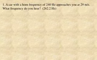
Factors influencing the magnitude of the Doppler shift frequency • The Doppler shift frequency occurs in the audible range. Example: A probe emits 5.0 MHz ultrasound beam striking the red blood cells traveling toward the transducer. The unit detects the reflected frequency to be 5.007 MHz. The transmitted & received frequencies are in the ultrasonic range, but the Doppler shift frequency is .007 MHz (7,000 Hz) (audible range). Typical Doppler shifts range: –10 kHz to +10 kHz
Factors influencing Doppler shift frequency • As the angle between the transducer & flow (COS ), the Doppler shift • If the RBCs are moving toward the transducer, the received frequency is higher than the transmitted frequency (shown as a positive Doppler shift). • If the RBCs are moving away from the transducer, the received frequency is lower than the transmitted frequency (shown as a negative Doppler shift).
Factors influencing Doppler shift frequency • If there is no motion of the RBCs, the reflected frequency = transmitted frequency; the Doppler shift is zero. • The faster the flow velocity, the higher the Doppler shift. Flow speed & Doppler shift, with vessel diameter2. • If there is a in concentration of RBCs or if you are performing the Doppler exam of the vessel off to one side, there may be a in intensity (hard to hear & see on spectral display).
Factors influencing Doppler shift frequency • Since the RBCs are much smaller than the wavelength of the sound beam, Rayleigh scattering occurs. • the transducer frequency will scattering & the Doppler shift • Although higher frequencies produce more scatter, they are attenuated more rapidly.
Factors influencing Doppler shift frequency • Since these reflectors are very weak in intensity, lower frequency transducers may be needed to obtain Doppler information at deeper depths. • Modern transducer technology takes advantage of the wide bandwidth emitted by the transducer by allowing imaging at high frequencies and then downshifting into lower frequencies to acquire the Doppler information.
Spectral Doppler Instrumentation Two Different Types • Continuous wave (CW) Doppler - 2 crystals located at slight angles to each other in the probe, one is for transmitting & the other for receiving • Pulsed wave (PW) Doppler - a single crystal element or an array transmits & receives the Doppler information.
Continuous wave (CW) Doppler 2 crystals located at slight angles to each other in the probe, one for transmitting & the other for receiving • The CW transducer is not damped • The transmitting crystal is transmitting sound 100% of the time
Continuous wave (CW) Doppler Transmitted beam zone & receiving zone overlap because the beam is directional
A moving structure in this region of overlap (sample volume) will create a Doppler signal. A CW instrument detects flow that occurs anywhere within the intersection of the beams.
With this large sample volume, CW Doppler systems can give complicated and confusing presentations if two or more different motions or flows are included in the sample volume, like when 2 vessels are being scanned at the same time.
No anatomical image is displayed, just a waveform on a monitor Only bi-directional instruments can distinguish between positive or negative Doppler shifts (forward & reverse flow)
Components of a CW Doppler system • Oscillator • Doppler detector • Phase quadrature detector • Spectrum analyzer • Spectral display device
Oscillator The oscillator produces the continuously alternating voltage with a 2-10-MHz frequency applied to the source transducer element. The oscillator that is set to equal the operating frequency of the transducer determines the ultrasound frequency.
The transducer assembly has a separate receiving transducer element that produces voltages with frequencies equal to the frequencies of the returning echoes. The reflected scatterer motion ultrasound and the source transducer will have different frequencies.
Doppler detector The Doppler detector detects the difference (Doppler shift) and relays it to the audio speaker at this frequency. Doppler shifts are typically 1/1000 of the operating frequency putting them in the audible range.
Doppler detector • Amplifies the echo voltages it receives, detects the Doppler shift information, & determines motion direction from the sign of the Doppler shift. • The difference is zero for echoes returning from stationary structures
Phase quadrature detector The phase quadrature detector determines the direction and divides the Doppler shift voltages into separates forward and reverse channels. The outputs are sent to separate loudspeakers so that forward & reverse Doppler shifts can be heard separately
Spectrum analyzer Doppler shifts are also sent through a spectrum analyzer to a spectral display to show positive & negative Doppler shifts above and below the display baseline, which represents zero Doppler shift for observation and evaluation.
Spectral display device The spectral display device is a cathode-ray tube where the Doppler shifts (that continually change over the cardiac cycle) are displayed as a function of time with appropriate real-time frequency-spectrum processing. These displays provide quantitative data for evaluating Doppler shifted echoes.
The displayed Doppler information is stored in digital memory before display so that it can be frozen and backed up over the last few seconds of information prior to freezing. To convert a display correctly from Doppler shift versus time to flow speed versus time, the Doppler angle must be accurately incorporated into the calculation process.
Wall filter (wall-thump filter) - is an electronic filter that allows the sonographer to adjust what level of frequencies are to be processed, thus eliminating high-intensity, low frequency Doppler shift echoes (clutter). • Frequently used in cardiac sonography to eliminate (reject) frequencies caused by heart or vessel wall and cardiac valve motion with pulsatile flow to an acceptable value.
Wall filter (wall-thump filter) -rejects the strong tissue structure echoes that would overwhelm the weaker echoes from the blood. These echoes have low Doppler shift frequencies because the structures do not move as fast as the blood does. The upper limit of the filter is adjustable over a range of about 25 to 3200 Hz. If not properly used, the filter can erroneously alter assumptions about the diastolic flow and distal flow resistance.
Other Types of CW • Hand-held, nondirectional devices are simpler, yielding only an audible output. • Analog zero-crossing detector devices
Analog zero-crossing detector devices - provide an instantaneous average Doppler shift that varies over cardiac cycle. This device counts how often the Doppler shift voltage changes from negative to positive per second. The higher the count,the higher the frequency.
The count is represented on the vertical axis & the horizontal axis represents time on a 2-d graph, on a strip-chart recorder that produces a hard copy. Some systems have spectral displays.
CW Advantages • ability to measure very high velocities • small probe sizes • ability to use high frequencies • large sample volume is helpful when searching for a Doppler maximum associated with a vascular or valvular stenosis
CW Disadvantages • lack of imaging • all Doppler shifts will be displayed so that specific vessels cannot be interrogated by themselves; this is a range ambiguity
Pulsed wave (PW) Doppler • - uses a single crystal element or an array to transmit & receive Doppler information • The required Doppler frequency shift detection requires longer ultrasound pulses than that used for imaging
Pulsed wave (PW) Doppler • Sample volume is placed in the vessel where the Doppler information is wanted • The operator adjusts the location & length of the range gate (sample gate, sample volume, range gate) to isolate the signal from the desired depth. • The width of the sample volume is equal to the beam width
Pulsed wave (PW) Doppler Sample Volume Placement • Increasing the gate size the # of Doppler signals picked up; longer gate lengths are used when searching for the desired vessel • the gate length results in a narrow range of velocities and flow location & are used for spectral analysis and evaluation.
Shorter gate length improves the quality of the spectral display