Download
1 / 33
330 likes | 802 Views
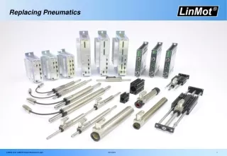
Jim Wright Team 949 2010 Team Workshops. Pneumatics. Map. Safety Parts Putting it together Wires and Controls. Safety. Battery is the most dangerous part of the kit It's dangerous if you do dangerous stuff to/around it. Drilling close to the battery is bad!

E N D
Jim Wright Team 949 2010 Team Workshops Pneumatics
Map • Safety • Parts • Putting it together • Wires and Controls
Safety • Battery is the most dangerous part of the kit • It's dangerous if you do dangerous stuff to/around it. • Drilling close to the battery is bad! • Shorting the contacts out on the frame is bad. • That is why we tape things up, remove the battery while working on the 'bot
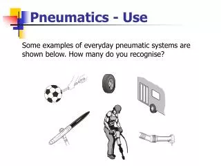
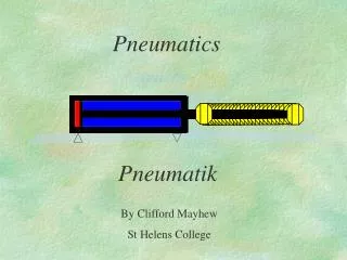
Piston/Cylinder • The Cylinder is naturally dangerous. • It moves fast • It's strong • It at first has a sharp point on the front of it. • A lot more care must be taken while working on a Pneumatic system.
Piston/Cylinder • Every member of the team must know where/how the cylinder is used! • If you don't need the Pneumatic system in the pits turn it off.
Piston/Cylinder • Only work on another teams robot if they have 20-30 seconds to tell you where the cylinders are. • Help them from a far if they are 'under the gun' and can't give you the 20-30 second overview. • 2001 or 2002 we almost lost a student to a cylinder.
Piston/Cylinder • Make sure the ends of the cylinder are connected to other parts of the robot. • Don't leave the sharp end unconnected.
Map • Safety • Parts • Putting it together • Wires and Controls
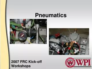
Compressor • Where the 120PSI pressure comes from. • Comes in two pieces, the compressor and the safety relief valve. • The two parts MUST be DIRECTLY connected. • The relief value MUST be adjusted, more on this later.
Tank • Can handle 120PSI • In 2010 you can have 4 of them. • Can be installed 'upstream' or 'downstream', more on this later.
Pressure Switch • Opens at 115psi • Closes at 95psi or lower. • Must be connected to the digital sidecar! • Can NOT be wired into the circuit with the compressor! • The robot inspector will have to do something dangerous with this, if you can put it in a spot that has 'good' access. This is up to your team.
Regulators • Law firm of Norgrin and Monnier • That is Monnier there in yellow. • Convert the pressure from 120PSI to from 0PSI to 60PSI • Norgrin has more experience so they go first in the pneumatic system. • Everything from Compressor to Norgrin is 'Upstream.' Everything from Norgrin onward is 'Downstream.' • Monnier is optional.
Gages • You need at least two and only get one. Barrow from another team! • You need one on Norgrin (reading 60PSI). • You need one upstream of Norgrin on it's own (reading 120PSI-ish). • Put both in a place you can read!
Release Valve • The item that make the whole system possible to put into your students hands. • Put this in a place where you can reach and safely open. • If this is left off your robot, your robot inspector will be shocked and they will talk about your team in the lunch room. This is how your team will receive and 'closer' inspection from the head inspector.
Brass fittings/Tubing • Things to connect the system together. • Vet' teams have tons of this. • Vet' teams may trade you colors. • Tubing is rated, rule of thumb, only use tubing from you kit of parts or another teams kit of parts. • Don't try to buy this on your own.
Valves • In 2010 You got a double throw valve in the kit. • Other valves are legal must be 60 PSI rated. Newer teams stick with: • FESTO VPLE18-M5H (bottom right) • SMC SY3240 (top right) • Bosch-Rexroth 840
Cylinders • Each year the legal selection may change. See the years Pneumatic manual. • Also see the manual for your free three cylinders. • As many of these puppies as you want. • Took 9 pages of parts to get to the one that does the work.
Rotary • Only moves 90 degrees. • But really really really darn fast 90 degrees.
Pneumatic Bumper • The cRIO and this are the only things that can be plugged into the 24 port of the power distribution box. • Every valve can be wired to this.
Map • Safety • Parts • Putting it together • Wires and Controls
Compressor on a relay • You compressor must be controlled by a relay, plugged into the digital side car. • The compressor's relay is turned on and off depending on the pressure switches reading. • This relay's (and only this relay's) fuse may be swapped out for a 20amp circuit breaker.
Debugging the leaks • Get a 'tube loop.' A tee connector where two ends are connected, leaving the free end to be plugged into things. • Check your manifold first. • Then work down from there. • Do this before you put the things on the robot. • Don't leave the 'tube loop' in the circuit for long periods of time, it's just there to check pressures using the gages.
Adjusting the safety relief valve • The brass plug is adjustable. • Three parts, the plug, the lock nut, the spring nut. • Unlock the lock nut by moving it away from the spring nut. • Loosen the spring nut to almost off the plug. • Then short the pressure switch leads. • Turn the robot on and then into enabled!
Adjusting the safety relief valve • Er um er. Are you sure about this.
Adjusting the safety relief valve • No really are you sure?
Adjusting the safety relief valve • OK it you insist. • Ah, the spring nut is loose so the safety valve is now constantly venting air so nothing it getting into the system. • Now tighten the spring nut so it vents at 128psi to 132psi, you can't get it to 130 exactly. • Tighten the lock nut... No wait!!! Turn the robot off, and vent the system. Then tighten the lock nut.
Map • Safety • Parts • Putting it together • Wires and Controls
We've touched on this before • Connect compressor to relay. • Connect pressure switch to digital in on the side car. • Connect the valves to the pneumatic bumper. • Pull up the valve library in the code and use it.
Finer control of the cylinder • Right now it's all out or all in. • On the order form there is a magnet option. • This allows you to know where in the cylinder the piston is and using a cleaver valve setup stop the throw of the cylinder at a different location.
Fin' • Safety!!!!!!!!!