Download
1 / 54
550 likes | 821 Views
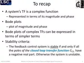
To recap. A system’s TF is a complex function R epresented in terms of its magnitude and phase Bode plots plot of magnitude and phase Bode plots of complex TFs can be expressed in terms of simpler terms Stability criteria:

E N D
To recap • A system’s TF is a complex function • Represented in terms of its magnitude and phase • Bode plots • plot of magnitude and phase • Bode plots of complex TFs can be expressed in terms of simpler terms • Stability criteria: • The feedback control system is stable if and only if all the poles of the closed loop transfer function have a negative real part. Otherwise the system is unstable. Matone: An Overview of Control Theory and Digital Signal Processing (3)
To recap • Stability in terms of the open loop gain • A closed loop system is stable if the unity gain frequency is lower than the crossing. • Rule of thumb: the system is (almost always) stable if at the unity gain frequency • How close to instability is a system? • Gain and phase margin • Typical compensators • Phase-lag • Phase-lead • “Boost” Matone: An Overview of Control Theory and Digital Signal Processing (3)
SIMULINK θ vr e + f H - K - + v G c • Simulating systems in the time-domain • Let’s refer back to the cruise control example • Parameters used previously Matone: An Overview of Control Theory and Digital Signal Processing (3)
OL TF bode plot cruise_freqdomain.m UGF @160 mHz Matone: An Overview of Control Theory and Digital Signal Processing (3)
Building the model First we need to model the response of the car to an input force . This was previously described by transfer function was derived from SIMULINK simulates this differential equation Matone: An Overview of Control Theory and Digital Signal Processing (3)
Building the model • Type simulink at the MATLAB prompt >> simulink • The “Simulink Library Browser” window opens. • File → New → Model • The model window opens Matone: An Overview of Control Theory and Digital Signal Processing (3)
Building the model • The relationship between and is simply . Add the Integrator block by selecting it and dragging it to the model window. The integrator block is in the simulink library browser under the continuous section. • Extend the signal in and signal out lines, double click on top of each line and label them as and Matone: An Overview of Control Theory and Digital Signal Processing (3)
Building the model • Re-arranging terms : the change in velocity is times . In the library browser, under the math operations section, select and drag the Gain block. • Connect its output to the integrator’s input. • Double-click on the gain block, set the gain value to , and click ok. • Double-click right under the gain block and label it as . Matone: An Overview of Control Theory and Digital Signal Processing (3)
Building the model • Under the math operations section, select and drag the Add block. • Connect the add block with the gain block • Double-click the add block and change the sign as shown in figure . • One input to the add block will be the engine force while the other will be the friction force Matone: An Overview of Control Theory and Digital Signal Processing (3)
Building the model • Add another Gain block, and change its orientation by selecting it, clicking on Format → Flip block • Double-click on it, set the gain to and click ok. • Double-click right under the block and re-name it as . • Connect the output of the integrator to the input gain block . • Connect the output of gain block with the negative input of the add block. Matone: An Overview of Control Theory and Digital Signal Processing (3)
Building the model • In the library browser, under the sources section, select and drag the Step block. • Connect the step block to the add block. • Double-click on the step block and set the final value to 500 (the same value we had used before) • In the Sinks section, select Scope and drag it to the window. Connect it to the output of the step block. • Select and drag a second scope and connect it to the integrator’s output • We are ready for the simulation Matone: An Overview of Control Theory and Digital Signal Processing (3)
Results cruiseG.mdl • At the MATLAB prompt set the parameters >> f=500;b=50;m=1000; • Under the Simulations tab, click Configuration parameters, set the end time to 100 and click ok. • Under the Simulations tab, click Start. • Once the simulation is finished, double-click on each scope, and graphing windows appear(you probably need to autoscale) • The time evolution is identical to the one we had obtained before. Matone: An Overview of Control Theory and Digital Signal Processing (3)
Results • SIMULINK is a time-domain simulation and handles linear and non-linear systems. The frequency-domain analysis presented so far can only handle linear models. To produce bode plots we need to linearize the model. • Erase the two scopes and the step block. • In the Sources section, add an In block and connect it to the add block. • In the Sinks section, add an Out block and connect it to the output of the integrator. • Save the model as “SubsystemG.mdl” • At the MATLAB prompt type the commands on the right which reproduce the transfer function we were using before >> [A,B,C,D]=linmod('subsystemG'); >> [num,den]=ss2tf(A,B,C,D); >> H=tf(num,den) Transfer function: 0.001 -------- s + 0.05 Note: A, B, C, D is a state space representation of the system Matone: An Overview of Control Theory and Digital Signal Processing (3)
Implementing feedback Create a new model calling it “cruise_control.mdl” Select and drag from the library the Ports & Subsystems → Subsystem block. Double-click on the subsystem block, erase the contents Double-click on the subsystemG.mdl model, select all and copy. Paste in the subsystem block. Matone: An Overview of Control Theory and Digital Signal Processing (3)
Implementing feedback cruise_control.mdl Matone: An Overview of Control Theory and Digital Signal Processing (3)
Let’s setup a SIMULINK model of the accelerometer shown before y B M k x Position y is with respect of the case, the case’s position is x. What is the transfer function between the input acceleration and the output y? Matone: An Overview of Control Theory and Digital Signal Processing (3)
Rule of thumb For a system represented by an nth order input/output ordinary differential equation it is necessary to integrate the highest derivative n times to obtain the output. Rearranging terms Matone: An Overview of Control Theory and Digital Signal Processing (3)
The model acc.mdl Matone: An Overview of Control Theory and Digital Signal Processing (3)
Results >> m=1;k=1;B=1; >> [A,B,C,D]=linmod('acc'); >> [num,den]=ss2tf(A,B,C,D); >> H=tf(num,den) Transfer function: 1 ----------- s^2 + s + 1 Which confirms our previous finding. Matone: An Overview of Control Theory and Digital Signal Processing (3)
Model the following LRC circuit Matone: An Overview of Control Theory and Digital Signal Processing (3)
Model the following LRC circuit Matone: An Overview of Control Theory and Digital Signal Processing (3)
Digital Signal Processing 1 • Moving to the digital world • Two classes of signals • Analog • Discrete • Analog signal • Denoted with • represents time in seconds • Discrete signal • Number sequence • is an integer, represents discrete instances in time digsig.m Matone: An Overview of Control Theory and Digital Signal Processing (3)
Types of sequences Unit sample sequence sequences.m Matone: An Overview of Control Theory and Digital Signal Processing (3)
Types of sequences Unit step sequence sequences.m Matone: An Overview of Control Theory and Digital Signal Processing (3)
Discrete systems • Linear time-invariant (LTI) system L • Satisfies the principle of superposition • The input-output pair, and , is invariant to a shift Matone: An Overview of Control Theory and Digital Signal Processing (3)
Discrete systems Any sequence can be written in terms of scaled and delayed unit sample sequences The response of an (LTI) system can then be re-written as Matone: An Overview of Control Theory and Digital Signal Processing (3)
Discrete systems is the unit sample or impulse response of LTI system Convolution Matone: An Overview of Control Theory and Digital Signal Processing (3)
Let’s compute the convolution between two sequences Let’s define and and let’s determine For Matone: An Overview of Control Theory and Digital Signal Processing (3)
Let’s compute the convolution between two sequences Let’s define and and let’s determine For Matone: An Overview of Control Theory and Digital Signal Processing (3)
Let’s compute the convolution between two sequences Let’s define and and let’s determine Using MATLAB to confirm results >> conv([3 2 1],[1 2 3]) ans = 3 8 14 8 3 Matone: An Overview of Control Theory and Digital Signal Processing (3)
Stability An LTI system is stable if and only if its impulse response is absolutely summable Matone: An Overview of Control Theory and Digital Signal Processing (3)
Correlation of sequences The correlation between two sequences and is defined as where • is the correlation (degree to which the two signals are similar) and • is the lag. Matone: An Overview of Control Theory and Digital Signal Processing (3)
Example conv_example2.m Generating two identical random sequences, one of them shifted by 50 samples. Matone: An Overview of Control Theory and Digital Signal Processing (3)
Example conv_example2.m Taking the correlation between them using MATLAB’s xcorr command we find highest correlation at lag 50. Matone: An Overview of Control Theory and Digital Signal Processing (3)
Example >> [r,lags]=xcorr(x,y); >> plot(lags,r,'bo') or >> r2=conv(x,fliplr(y),'same'); conv_example2.m Using MATLAB’s xcorr or conv command. Matone: An Overview of Control Theory and Digital Signal Processing (3)
Exercise In a certain concert hall, echoes of the original audio signal are generated due to reflections at the walls and ceiling. The audio signal experienced by the listener is a combination of and its echoes. Let where k is the amount of delay in samples and is its relative strength. Estimate the delay assuming the original signal is a Sine-Gaussian with , and . Matone: An Overview of Control Theory and Digital Signal Processing (3)
ex28.m Matone: An Overview of Control Theory and Digital Signal Processing (3)
Signal Energy The energy of a sequence is given by Matone: An Overview of Control Theory and Digital Signal Processing (3)
Differential to difference equations x(t) y(t) In the analog world: Matone: An Overview of Control Theory and Digital Signal Processing (3)
Differential to difference equations In the limit The original differential equation is approximated by a difference equation In the digital world: Matone: An Overview of Control Theory and Digital Signal Processing (3)
>> diff(x) In the limit difference.m Matone: An Overview of Control Theory and Digital Signal Processing (3)
>> diff(x) In the limit difference.m Matone: An Overview of Control Theory and Digital Signal Processing (3)
Difference equations • In general, a difference equation is of the form • where is the input sequence • is the output sequence and • and are the coefficients of and respectively. • The MATLAB filter command solves the difference equations numerically – filtering input sequence >> y = filter(b, a, x) Matone: An Overview of Control Theory and Digital Signal Processing (3)
Impulse response To generate the impulse response of an LTI system described by the difference equation use the filter command: >> h = filter(b, a, delta) By plotting you can visualize if the system is stable Matone: An Overview of Control Theory and Digital Signal Processing (3)
Example An LTI system is described by the following difference equation Plot the impulse response for and determine if system is stable. Matone: An Overview of Control Theory and Digital Signal Processing (3)
Example An LTI system is described by the following difference equation Plot the impulse response for and determine if system is stable. Generating the delta function with MATLAB >> x = zeros(1,100); >> x(1) = 1; >> plot(x,'bo-') ex29.m Matone: An Overview of Control Theory and Digital Signal Processing (3)
Example An LTI system is described by the following difference equation Plot the impulse response for and determine if system is stable. Generating the response >> b=1; >> a=[1 -1 0.9]; >> h=filter(b,a,x); >> plot(h,'bo-') System is stable ex29.m Matone: An Overview of Control Theory and Digital Signal Processing (3)
Exercise An LTI system is described by the difference equation Plot its impulse response and determine the stability of the system. Matone: An Overview of Control Theory and Digital Signal Processing (3)
ex216.m Generating the response >> b=[1 2 0 1]; >> a=[1 -0.5 0.25]; >> h=filter(b,a,); >> plot(h,'b-') Matone: An Overview of Control Theory and Digital Signal Processing (3)
Cruise control case Direction of motion • Physical system described by the following equation of motion • Simplifying and assuming friction force is proportional to speed Normal force (n) Force from engine (f) Friction force (ffr) Weight (mg) Matone: An Overview of Control Theory and Digital Signal Processing (3)