Download
1 / 32
320 likes | 516 Views
State Machine Signaling. Timing Behavior Glitches/hazards and how to avoid them FSM Partitioning What to do when the state machine doesn’t fit! State Machine Signaling Introducing Idle States (synchronous model) Four Cycle Signaling (asynchronous model) Dealing with Asynchronous Inputs

E N D
State Machine Signaling • Timing Behavior • Glitches/hazards and how to avoid them • FSM Partitioning • What to do when the state machine doesn’t fit! • State Machine Signaling • Introducing Idle States (synchronous model) • Four Cycle Signaling (asynchronous model) • Dealing with Asynchronous Inputs • Metastability and synchronization CS 150 - Spring 2004 – Lec #22 – Signaling - 1
Mean Midterm #1 Results Midterm 1 25 20 15 Number 10 5 0 38 39 40 41 42 43 44 45 46 47 48 49 50 Score CS 150 - Spring 2004 – Lec #22 – Signaling - 2
Midterm #2 Results -2 SD Mean +2 SD -1 SD +1 SD CS 150 - Spring 2004 – Lec #22 – Signaling - 3
Combined Midterm Results -2 SD Mean -1 SD +1 SD +2 SD CS 150 - Spring 2004 – Lec #22 – Signaling - 4
A B C D F Momentary Changes in Outputs • Can be useful—pulse shaping circuits • Can be a problem—incorrect circuitoperation (glitches/hazards) • Example: pulse shaping circuit • A' • A = 0 • delays matterin function D remains high for three gate delays after A changes from low to high F is not always 0 pulse 3 gate-delays wide CS 150 - Spring 2004 – Lec #22 – Signaling - 5
+ resistor A B open switch C D Oscillatory Behavior • Another pulse shaping circuit close switch initially undefined open switch CS 150 - Spring 2004 – Lec #22 – Signaling - 6
Hazards/Glitches • Hazards/glitches: unwanted switching at the outputs • Occur when different paths through circuit have different propagation delays • As in pulse shaping circuits we just analyzed • Dangerous if logic causes an action while output is unstable • May need to guarantee absence of glitches • Usual solutions 1) Wait until signals are stable (by using a clock): preferable (easiest to design when there is a clock – synchronous design) 2) Design hazard-free circuits: sometimes necessary (clock not used – asynchronous design) CS 150 - Spring 2004 – Lec #22 – Signaling - 7
1 1 0 1 0 0 1 1 0 0 1 1 0 0 Types of Hazards • Static 1-hazard • Input change causes output to go from 1 to 0 to 1 • Static 0-hazard • Input change causes output to go from 0 to 1 to 0 • Dynamic hazards • Input change causes a double changefrom 0 to 1 to 0 to 1 OR from 1 to 0 to 1 to 0 CS 150 - Spring 2004 – Lec #22 – Signaling - 8
A S B S' Static Hazards • Due to a literal and its complement momentarily taking on the same value • Thru different paths with different delays and reconverging • May cause an output that should have stayed at the same value to momentarily take on the wrong value • Example: A B F S S' F hazard static-0 hazard static-1 hazard CS 150 - Spring 2004 – Lec #22 – Signaling - 9
A F 3 2 B 1 C Dynamic Hazards • Due to the same versions of a literal taking on opposite values • Thru different paths with different delays and reconverging • May cause an output that was to change value to change 3 times instead of once • Example: A C B1 B2 B3 F hazard dynamic hazards CS 150 - Spring 2004 – Lec #22 – Signaling - 10
No Glitch in this case This is the fix Glitch in this case Eliminating Static Hazards • Following 2-level logic function has a hazard, e.g., when inputs change from ABCD = 0101 to 1101 CS 150 - Spring 2004 – Lec #22 – Signaling - 11
Eliminating Dynamic Hazards • Very difficult! • A circuit that is static hazard free can still have dynamic hazards • Best approach: • Design critical circuits to be two level and eliminate all static hazards • OR, use good clocked synchronous design style 1 0 1 \A G1 B 0 1 Slow G3 1 0 1 1 0 \B 1 0 1 0 G2 \C 1 0 G5 F 1 0 A 1 0 G4 \B 1 0 V ery slow CS 150 - Spring 2004 – Lec #22 – Signaling - 12
FSM Partitioning • Why Partition? • What if programmable logic is limited in number of inputs and outputs that can be used in a particular device? • For PLAs, the number of product terms are limited, thus limiting the complexity of the next state and output functions CS 150 - Spring 2004 – Lec #22 – Signaling - 13
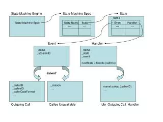
Partitioning the State Machine • Suppose that FSM is partitioned so that states at the right are in one partition and states at the left are in the other • How do you support intersignaling between the state machine partitions? • It is usually a good idea to partition the machine so there are as few cross links as possible (min cut set in graph theoretic terms) CS 150 - Spring 2004 – Lec #22 – Signaling - 14
Partitioning the State Machine • Solution: introduce idle states SA and SB • Machine at left enters SA allowing machine at right to exit SB • When machine at right returns to SB, machine at left exits SA CS 150 - Spring 2004 – Lec #22 – Signaling - 15
Rules for Introducing Idle States CS 150 - Spring 2004 – Lec #22 – Signaling - 16
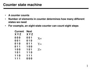
Example: Partitioning the Up/Down Counter CS 150 - Spring 2004 – Lec #22 – Signaling - 17
Example Partitioning: Traffic Light Controller • Main Controller vs. Counter/Timer • ST triggers transfer of control • TS or TL triggers return ofcontrol T00 T19 [TL] ST Reset T01 T09 T10 T18 (TL•C)' HG TL•C / ST TS / ST T02 T08 T11 T17 HY FY TS' TS' T03 T07 T12 T16 TS / ST TL+C' / ST FG T04 [TS] T06 T13 T15 (TL+C')' (a) Main controller T05 T14 (b) Counter/timer CS 150 - Spring 2004 – Lec #22 – Signaling - 18
Partitioned FSM Block Diagram • Interface between the two partitions are the signals ST, TS, TL • NOTE: Main Controller and Timer use the same clock and are operating in a synchronous mode HRHYHG FRFYFG resetC traffic light controller ST TS TL timer CS 150 - Spring 2004 – Lec #22 – Signaling - 19
Generalized Inter-FSM Signaling • Interlocked Synchronized Signaling CS 150 - Spring 2004 – Lec #22 – Signaling - 20
Asynchronous Signaling • Also known as “speed-independent” signaling • Requester/client/master vs. Provider/Server/Slave CS 150 - Spring 2004 – Lec #22 – Signaling - 21
Asynchronous Signaling • First consider the common clock case (synchronous) • Master asserts Request • Slave recognizes request, processes request, indicates completion by asserting Acknowledgement • Master accepts results, removes Request • Slave see Request removed, removes Acknowledge CS 150 - Spring 2004 – Lec #22 – Signaling - 22
Asynchronous Signaling • What if Slave can’t respond in single cycle? Solution: Wait signaling • Slave inhibits master by asserting wait • When slave unasserts wait, master knows request has been processed, and can latch results CS 150 - Spring 2004 – Lec #22 – Signaling - 23
True Asynchronous Signaling • Now remove the assumption of a single common clock • How do we make sure that receiver has seen the sender’s signal? Solution: Interlocked signaling • Four cycle signaling: assert Req, process request, assert ack, latch result, remove Req, remove Ack and start again • Sometimes called “Return to Zero” signaling 1 3 Req Data 4 2 Ack CS 150 - Spring 2004 – Lec #22 – Signaling - 24
True Asynchronous Signaling • Alternative scheme: Two-Cycle Signaling • Non-return-to-zero signaling • Transaction start by Req lo-to-hi, finishes Ack lo-to-hi • Next transaction starts by Req hi-to-lo, finishes Ack hi-to-lo • Requires EXTRA state to keep track of the current sense of the transitions—faster than 4 cycle case, but usually involves more hardware 1 1 Req Data 2 2 Ack CS 150 - Spring 2004 – Lec #22 – Signaling - 25
Self-Timed Circuits Uses Req/Ack signaling as described Components can be constructed with NO internal clocks Determines on its own when the request has been processed Concept of the delay line simply slows down the pass through of the Req to the Ack—usually matched to the worst case delay path Becoming MORE important for large scale VLSI chips were global clock distribution is a challenge True Asynchronous Timing Input Output Combinational logic Req Ack Delay CS 150 - Spring 2004 – Lec #22 – Signaling - 26
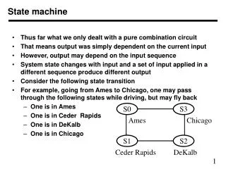
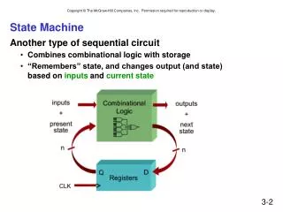
Metastability and Asynchronous inputs • Clocked synchronous circuits • Inputs, state, and outputs sampled or changed in relation to acommon reference signal (called the clock) • E.g., master/slave, edge-triggered • Asynchronous circuits • Inputs, state, and outputs sampled or changed independently of a common reference signal (glitches/hazards a major concern) • E.g., R-S latch • Asynchronous inputs to synchronous circuits • Inputs can change at any time, will not meet setup/hold times • Dangerous, synchronous inputs are greatly preferred • Cannot be avoided (e.g., reset signal, memory wait, user input) CS 150 - Spring 2004 – Lec #22 – Signaling - 27
Synchronization Failure • Occurs when FF input changes close to clock edge • FF may enter a metastable state – neither a logic 0 nor 1 – • May stay in this state an indefinite amount of time • Is not likely in practice but has some probability logic 1 logic 0 logic 0 logic 1 oscilloscope traces demonstrating synchronizer failure and eventual decay to steady state small, but non-zero probability that the FF output will get stuck in an in-between state CS 150 - Spring 2004 – Lec #22 – Signaling - 28
Dealing with Synchronization Failure • Probability of failure can never be reduced to 0, but it can be reduced (1) slow down the system clock: this gives the synchronizer more time to decay into a steady state; synchronizer failure becomes a big problem for very high speed systems (2) use fastest possible logic technology in the synchronizer:this makes for a very sharp "peak" upon which to balance (3) cascade two synchronizers: this effectively synchronizes twice (both would have to fail) Q asynchronous input synchronized input D Q D Clk CS 150 - Spring 2004 – Lec #22 – Signaling - 29 synchronous system
D Q D Q D Q D Q D Q Handling Asynchronous Inputs • Never allow asynchronous inputs to fan-out to more than one flip-flop • Synchronize as soon as possible and then treat as synchronous signal Clocked Synchronizer Synchronous System Q0 Q0 Async Async Input Input Clock Clock Q1 Q1 Clock Clock CS 150 - Spring 2004 – Lec #22 – Signaling - 30
Handling Asynchronous Inputs (cont’d) • What can go wrong? • Input changes too close to clock edge (violating setup time constraint) In Q0 Q1 CLK In is asynchronous and fans out to D0 and D1one FF catches the signal, one does not inconsistent state may be reached! CS 150 - Spring 2004 – Lec #22 – Signaling - 31
Signaling Summary • Glitches/Hazards • Introduce redundant logic terms to avoid them OR use synchronous design! • FSM Partitioning • Replacing monolithic State Machine with simpler communicating state machine • Technique of introducing idle states • Machine-to-machine Signaling • Synchronous vs. asynchronous • Four vs. Two Cycle Signaling • Asynchronous inputs and their dangers • Synchronizer failure: what it is and how to minimize its impact CS 150 - Spring 2004 – Lec #22 – Signaling - 32