Download

1 / 20
350 likes | 1.36k Views
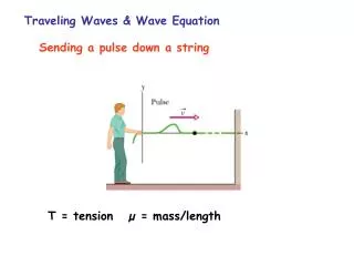
Wave Equation Applications. 2011 PDCA Professor Pile Institute. Patrick Hannigan GRL Engineers, Inc. WAVE EQUATION APPLICATIONS. Develop Driving Criterion Blow Count for a Required Ultimate Capacity Blow Count for Capacity as a Function of Energy / Stroke. Check Driveability

E N D
Wave Equation Applications 2011 PDCA Professor Pile Institute Patrick Hannigan GRL Engineers, Inc.
WAVE EQUATION APPLICATIONS Develop Driving Criterion Blow Count for a Required Ultimate Capacity Blow Count for Capacity as a Function of Energy / Stroke Check Driveability Blow Count vs. Penetration Depth Driving Stresses vs Penetration Depth Determine Optimal Driving Equipment Driving Time Refined Matching Analysis Adjust Input Parameters to Fit Dynamic Measurements
REQUIRED INFORMATION • Hammer • Model • Stroke and Stroke Control • Any Modifications • Driving System • Helmet Weight (including Striker Plate & Cushions) • Hammer Cushion Material (E, A, t, er) • Pile Cushion Material (E, A, t, er)
REQUIRED INFORMATION • Pile • Length, • Cross Sectional Area • Taper or Other Non-uniformities • Specific Weight • Splice Details • Design Load • Ultimate Capacity • Pile Toe Protection
REQUIRED INFORMATION • Soil • Boring Locations with Elevations • Soil Descriptions • N-values or Other Strength Parameters vs Depth • Elevation of Excavation • Elevation of Pile Cut-off • Elevation of Water Table • Scour Depth or Other Later Excavations
Ram Anvil Pile Driving and Equipment Data Form
Example Problems FHWA Pile Manual – Chapter 16 #1 - General Bearing Graph #2 – Constant Capacity / Variable Stroke #3 – Tension and Compression Stress Control #4 – Use of Soil Setup #5 – Drivability Studies #6 – Driving System Characteristics #7 – Assessment of Pile Damage #8 – Selection of Wall Thickness #9 – Evaluation of Vibratory Driving GRLWEAP Program – 23 Examples
GRLWEAP Standard Examples • Example 1: Generation of a Bearing Graph for an Open End Diesel Hammer • Example 2: Closed End Hammer, Non Uniform Pile, Equipment Check • Example 3: Concrete Pile, ECH, Tension Stress Check • Example 4: Diesel Hammer Input • Example 5: Pile Segment and Damping Input • Example 6: Comparison of Damping Parameters • Example 7: Reduced Diesel Fuel and Quake Variation • Example 8: Effects of Splice/Slack on Pile Stress • Example 9: Residual Stress Analysis (RSA) • Example 10: Pile Damping, Long Piles, Diesel Hammer Performance • Example 11: Drivability Analysis (Blow Count vs. Depth) • Example 12: Inspector's Chart or Constant Capacity Option • Example 13: Composite Pile, Second Toe and Critical Stresses • Example 14: Two Pile Analysis Considering Follower with Long Skirt • Example 15: Mandrel Driven Pile • Example 16: Drilled Shaft Test with No Helmet • Example 17: Vibratory Hammer Analysis • Example 18: Pile and Hammer Gravity Changes • Example 19: Static Soil Analysis • Example 20: Steel Follower on Concrete Pile • Example 21: Using ST and Variable Pile Cushion Stiffness • Example 22: Drivability Analysis for a large, non-uniform pipe pile – Offshore Wave 2010 • Example 23: CPT Based Static Analysis Input Example
GRLWEAP Example 1 Solution ) 27.9 ksi 8.4 ft 330 kips 85 blows / ft
GRLWEAP Example 2 Solution ) 8.4 ft 85 blows / ft
GRLWEAP Example 4 Problem Hammer: Vulcan 08: 35.3 kJ (26 ft-kips) Hammer Cushion: 216 mm (8.5 inch) Hamortex Helmet: 11.6 kN (2.6 kips) Pile Cushion: 152 mm (6 inch) Plywood Depth (m) (ft) 0 0 Pile: Square Precast Concrete Pile Length 16 m (52.5 ft) Pile Penetration 15 m (49.2 ft) 305 mm (12 inch) Ultimate Capacity 1340 kN (300 kips) 10 4 Stiff Clay cu = 70 kPa (1.5 ksf) Setup Factor = 1.33 20 8 30 Shaft Resistance, 92% Uniform Distribution 1233 kN (276 kips) 12 40 50 16 Toe Resistance, 8% 107 kN (24 kips) 60 20
Example 4 Solution 81 blows / ft without anticipated soil set-up (300 kips) 42 blows / ft with anticipated soil set-up (225 kips)
GRLWEAP Example 6 Problem Hammer: ICE 42-S: 56.9 kJ (42 ft-kips) or Vulcan 014: 56.9 kJ (42 ft-kips) Hammer Cushion: Varies Helmet: Varies Depth (m) (ft) 0 0 Pile: Closed End Pipe Pile Length 20 m (66 ft) Pile Penetration 16 m (52.5 ft) 355 mm (14 inch) x 9.5 mm (3/8 inch) Ultimate Capacity 1800 kN (405 kips) 10 4 Loose Silty Fine Sand 20 8 30 Shaft Resistance, 30% Triangular Distribution 540 kN (121 kips) 12 40 50 16 Very Dense Silty Fine Sand Toe Resistance, 70% 1260 kN (284 kips) 60 20
GRLWEAP Example 6 Solution 99 bl/ ft 228 bl/ ft