Download
1 / 52
520 likes | 616 Views
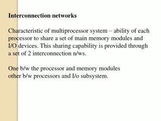
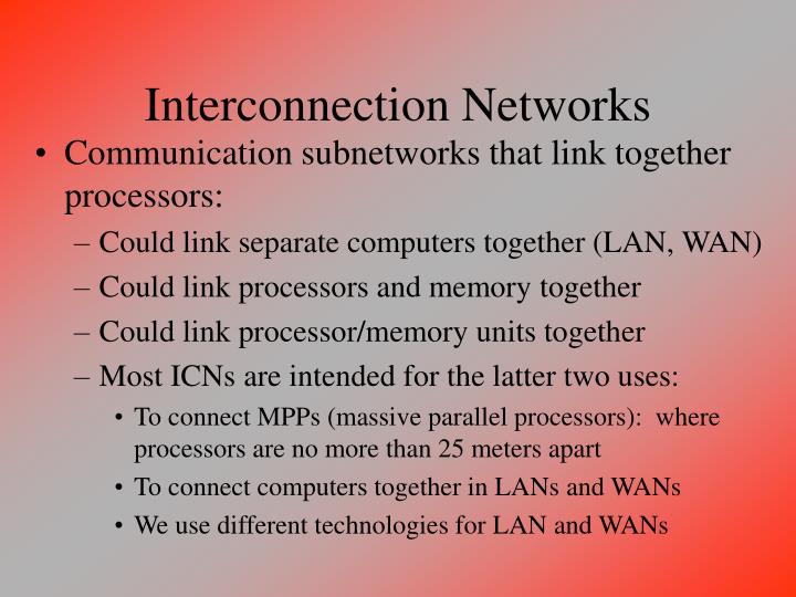
Interconnection Networks. Communication subnetworks that link together processors: Could link separate computers together (LAN, WAN) Could link processors and memory together Could link processor/memory units together Most ICNs are intended for the latter two uses:

E N D
Interconnection Networks • Communication subnetworks that link together processors: • Could link separate computers together (LAN, WAN) • Could link processors and memory together • Could link processor/memory units together • Most ICNs are intended for the latter two uses: • To connect MPPs (massive parallel processors): where processors are no more than 25 meters apart • To connect computers together in LANs and WANs • We use different technologies for LAN and WANs
Network Cultures • LAN represents a network of workstations in fairly close proximity (within a mile) • Uses - file transfer, communication, transfers should be fairly quick (order of seconds or less) • WAN represents long distance telecommunication • Uses - file transfer, communication, transfers do not have to be quick (order of seconds or longer) • The MPP represents a specialized computer with more than 1 processor (possibly hundreds or thousands) • Uses - parallelize applications, transfers must be very fast (on the order of main memory fetches)
A Simple Network • See figure 7.2 • Here, two computers are connected directly together through some form of wire • Each computer has a queue to hold data • For one machine to get data from another, it must first send a request containing the data address • When a request arrives at the other machine, it must send a reply with the data
Messages • In our simple example, 1 bit is used to denote if a message is a reply from a previous message, or a new message • This bit makes up a descriptor of the information, usually known as a header (or a trailer) • Most communications will require more elaborate headers and/or trailers • The form and meaning of the header/trailer is determined by the protocol -- the language or rules used for communications • Here, it is simple because there are only 2 directly-connected computers
Software for Networks • All networks require not only the hardware (the physical connections, bus, routing mechanisms) but also software (usually part of the OS) • Used for: • Preparing the message (the protocol, which includes creating the header/trailer and sending the message off) • Protection - to ensure that the proper process receives the message • Reliable deliver - to ensure that the message is received by seeking a reply, or by a time-out mechanism, and to ensure that there are no errors in the message (using a checksum approach)
Software Steps • To send a message: • Application software copies data to be sent into an OS buffer • OS creates header/trailer, including the checksum which must be calculated • OS sends data to network interface (hardware) • To receive a message: • OS copies data from network interface into a buffer • OS calculates checksum, acknowledges receipt or deletes data (if error, assuming sender will resend) • OS copies data to user’s address space and signals application to continue
Acknowledgements • The sender gets an acknowledgement from the receiving machine, it releases the copy of the message (deletes it) from the buffer • If the sender times out (that is, if a time period elapses prior to receiving an acknowledgement), the sender resends the data and restarts the timer • Therefore, the OS must retain the message in the buffer after sending, at least for a time
Enhanced Message Format • See figure 7.4 • Because of the possibility of resending the message after a time out, we make the header more complex • Here, we require the sender to first request a reply before sending the message to ensure that the computer and network are available: • 00 = request 01 = reply • 10 = acknowledge request 11 = acknowledge reply • Also note the checksum as the message trailer
Performance Parameters • Bandwidth - maximum rate at which networks can propagate information once the message enters the network (also called throughput) • Time of flight - time for first bit to arrive -- includes delays for repeaters and other hardware, and the physical limitation of transmission -- that is, speed of light or speed of current over wire, etc • Transmission time - time for the message to pass through the network (not including time of flight) and equal to the size of the message divided by bandwidth
More Performance Parameters • Transport latency - sum of time of flight and transmission time - time the message spends in the ICN itself (not including overhead below) • Sender overhead - time for processor to inject message into network (includes hardware and software components) • Receiver overhead - time for processor to pull message out of network and may include a processor interrupt to move message to appropriate place
Total Latency • The total latency of a message is the time between a process issuing a transfer command and the time it is placed in a location accessible by the counterpart process: • Total latency = Sender overhead + Time of flight + Message size/Bandwidth + Receiver overhead • In many networks, the overheads dominate the latency (in part because time of flight and bandwidth are dictated by hardware, overhead by software)
Example • Network with bandwidth of 10 Mbits/sec • Sending overhead = 230 microsec • Receiving overhead = 270 microsec • Two machines 100 meters apart • Message = 1000 bytes (including header) • Calculate the total latency to send the message, and then do the same assuming 1000 km distance • Note that the speed of light is 299,792.5 km/second and that the transmission speed along the medium is 50% of the speed of light
Solution • Total latency for 100 meters = 230 microsec + .1 km/.5*299792.5 km/sec + 1000/10Mbit/sec + 270 microsec = 230 + .67 + 800 + 270 microsec = 1301 microsec • Total latency for 1000 km = 230 microsec + 1000 km/.5*299792.5 km/sec + 1000/10Mbit sec + 270 microsec = 230 + 6671 + 800 + 270 microsec = 7971 microsec • Notice that 500 microsec is OS overhead which amounts for over 1/3 of the time for the first example (a much less impact on the second ex) and 800 microsec is required for the bandwidth of this network given the message size
Consequences of Longer Distances • The previous example treated the 100 meters and 1000 kilometers equivalently in terms of the parameters of transmission • However, longer distances carry a greater possibility of error and so more time-consuming protocols are used in an attempt to reduce errors • This will increase the latency because of increased overhead
Updated Latency Formula • We combine the two overheads (sender, receiver) and the time of flight into a single overhead term giving • Total latency = overhead + mess. size/bandwidth • Then, effective bandwidth = mess. size/latency • The magnitude of the latency affects the program (small latencies do not impact performance, large latencies do requiring that the latency be “hidden”)
Example • Plot the effective bandwidth vs. message size for overheads of 1, 25, and 500 microsec • Vary message sizes from 16 bytes to 4 Mbytes • For what message sizes is the effective bandwidth virtually the same as the raw network bandwidth? • Assuming 500 microsec for overhead, what message sizes is the effective bandwidth less than 10Mbits/sec?
Solution • See Figure 7.6 for the graph. • Message sizes must be at least 4 Mbytes for the effective bandwidth to be about the same as the network bandwidth • So, the high overhead can only be “ignored” for messages of fairly large sizes (megabytes or more) • Thus, we must either be satisfied with a network that only carries large messages, or reduce the overhead substantially!
Message Sizes • Aside from FTP (and Internet browsers), most programs, including Email, send smaller sized messages than bigger ones • This is especially true of an ICN connecting multiprocessors together, a message may be a single variable (1-16 bytes) • See figure 7.7 for an example of message sizes transmitted using NFS at UC Berkeley - 95% of messages are less than 192 bytes
Connecting Computers to Networks • Primary questions to answer: • Where do you connect the network to the computer? • Which media are available to connect computers together? • What issues arise if you want to connect more than 2 computers? • What practical issues arise for commercial networks? • We will examine some of these questions over the next 4 sections of chapter 7
Connecting Computer and Network • This question raises many issues including: • where - I/O bus, memory bus, other • whether interrupts and polling are required for communications • whether communications requires invoking the OS or how to avoid this if possible • Every computer has a hierarchy of buses -- the physical connection is made to one of these buses, which one?
Bus connections • A PC will have a memory bus, PCI bus (fast I/O), ISA bus (slow I/O) • I/O buses have open standards and less stringent electrical requirements • Memory buses have higher bandwidth, lower latency -also note that if connected to memory bus, this may require flushing cache for every message received! • MPPs will have their network connections over memory buses (usually) • LANs and WANs will have their network connections over slower I/O buses
Physical Connections • The physical location to connect the bus might be: • standard network card through slots in motherboard • motherboard directly (restricts the type of network the computer can be connected too)
Software Connection • Similarly, how is the network viewed from software? • If connection to I/O bus, then the network might be addressed using Programmed I/O • If connection to memory bus, then the network might be addressed using DMA (memory-mapped removing the need for address translations) • Larger messages are better sent via DMA • Programmed I/O typically handles single byte or small block transfers
ICN Media • Three common media: • Twisted pair - two insulated copper wires (about 1 mm thick) twisted together to reduce electrical interference (two parallel lines form an antenna, two twisted lines do not • Coaxial cable - single, stiff copper wire surrounded by insulating material and then surrounded by cylinditrical conductor • Fiber optics - flexible glass that includes a light source at one end (LED or laser diode) and a light detector at the other (photodiode)
More on these Media • Twisted pair - used for telephone system and very cheap • Coaxial cable - higher bandwidth and better insulation against noise, used for cable tv • Fiber optics - highest bandwidth and most noise-resistant, a replacement media for the phone companies
Duplex Transmission • A one-way transmission media is called simplex • A two-way transmission media is called duplex • Fiber optic cable are simplex, coaxial cable and twisted pair are duplex (although not simultaneously, which is known as full-duplex) • To solve this problem, fiber optic cable requires two cables per connection
Two Forms of Fiber Optics • Light is bent or refracted at interfaces and so the light slowly disperses as it travels down the cable unless the diameter is limited to one wavelength thickness • Multimode fiber - allows the light to be dispersed using inexpensive LEDs -- transmits up to 2 km at about 600 megabites/sec • Single-mode fiber - single-wavelength fiber which requires more expensive light transmitters (laser diodes) -- gigabits/sec over hundreds of kilometers
Connecting Fiber Optics • The single-mode fiber is more difficult to connect (and also less reliable) and so most computer networks that use fiber optics, use the multimode fiber • The connection is more difficult to make than with wire, so the connections are “taps” that are fused onto the fiber or by an active repeater - a device to translate information into light and back
Example • 100 magnetic tapes each containing 10 GB and enough tape readers to keep the network busy. How long would it take to transmit the data over 1 km using each of the media? • Twisted wire = 1000 * 1024 * 8 Mb / 1 Mb/sec = 8192000 seconds = 95 days! • Coaxial cable = 1000 * 1024 * 8 MB / 10 Mb/sec = 819200 seconds = 9.5 days • Multimode fiber = 1000 * 1024 * 8 MB / 600 Mb/sec = 13653 seconds = 3.8 hours • Single-mode fiber = 1000 * 1024 * 8 MB / 2000 Mb/sec = 4096 seconds = 1.1 hours
Connecting > 2 Computers • More interestingly is connecting more than 2 computers • This requires a shared network of some kind rather than the single line connecting two computers from figure 7.2 • Two general approaches, shared media vs. switched media • Shared media is a single bus or line that is shared among all nodes -- this is common in LANs and is often called an Ethernet
Shared Media • Needs a mechanism to coordinate communication so that only 1 message is sent at a time • If network is small, a central arbiter might work, but this is impractical for large networks or networks that are distributed over a great distance • Distributed arbitration means that a machine listens to the network first to see if it is in use and if not, then it can use the network • Network interfaces may have the ability to look for collisions and avoid or detect them to resend later by waiting a random amount of time
Switched Media • The network contains multiple paths and switches that route a message from one part of the network to another • These networks are more expensive but carry a higher bandwidth because there are less (or no) collisions -- they also have a larger latency due to the switches and logic involved in routing a message • Switched networks are common for MPP ICNs where speed is very critical, distance is typically short and number of nodes is usually small
Switch Topology • Crossbar - full connection between every node -- there are n paths between every set of nodes • Omega - a set of log n stages between n nodes, a total of n log n switches, each able to handle 2 inputs and 2 outputs -- there is 1 path between every set of nodes • Fat tree - a hybrid that provides more than 1 path but is more expensive (a compromise between the two extremes) • See figures 7.13 and 7.14 on pages 584-5
Distributed Switch Networks • In the previous networks, each processor is the same distance away from all others • Here, however, the topology places some nodes closer to others: • Ring - ethernet, each node is connected to the single network • Hypercube (or mesh or torus) - several paths between nodes, nearest neighbors have lesser latency
Performance of these topologies • Bisection bandwidth -- dividing the interconnect into two roughly equal parts • Cost - in terms of ports per switch and overall number of lines • For 64 nodes: • Bus Ring 2D torus 6-cube Full • Bisection 1 2 16 32 1024 • Ports/Swt NA 3 5 7 64 • Lines 1 128 192 256 2080
Example • All-to-all communication for 64 nodes (64 * 63 = 4032 messages) • Bus - transfer sequentially around the bus, 4032 messages in 4032 time units • Fully connected - all done in parallel, 4032 messages in 1 time unit • Ring - each node sends 1 message to each node in one direction, so each node sends 64 messages, each message takes 1 unit of time per distance (so, a node two computers away takes 2 time units to reach), each computer sending simultaneously -- Sum (1..64) if we send all in one direction, or Sum (1..32, 31..1) in bi-directional mode = 1024 time units
Example Continued • 2D Torus - 8 rows, 8 columns, so its like 8 rings. To send within 1 row is Sum (1..4,3..1) = 16. To send a message to all elements requires first sending in the given row, then shifting those messages up 1 row and repeating, then shifting up 2 rows and repeating, etc… = 16 + (8*1 + 16) + (8*2 + 16) + (8*3 + 16) … (again, being bi-directional, once we get to 8*4, we go back down to 8*1…) = 256 • 6-cube - Neighboring messages take 1 unit, messages to nodes 2-away take 2 units, etc… Each node has 6 neighbors, 36 2-away neighbors, etc…, a total of 132 (see page 589 for full explanation) • See figure 7.18 for summary figure
Circuit vs. Packet switching • Essentially the same as connection-oriented (an operator makes a connection between two nodes) and connectless (message finds its own route) • For telephone, messages can be frequency-division multiplexed -- that is, two or more messages can be carried on the same line by having them multiplexed over frequency and time • Since data transmission is more “burst-oriented”, computer communication cannot do this efficiently and so a packet-switched or connectionless method is better
Routing: Delivering Messages • In shared media, a message has a header that determines the destination -- either to all nodes, or one specific node • Computers listen to the network for messages directed towards it and ignore all others • But for switch-based communications, the switches must make decisions on routing
Approaches • Source-based routing - message specifies the path as well as the destination • Virtual circuit - circuit is established prior to communication • Destination-based routing - switches decide how to route the message • Deterministic - message always follows same path between two given nodes • Adaptive - message may follow different paths • Randomized - network picks randomly between paths (any of which can be taken to reach destination)
Congestion Control • Network usage is not determinable, any packet-switched network might have congestion causing a node to receive more than 1 packet at a time • This may require that switches contain buffers to store packets although this is expensive • Methods to reduce congestion include: • Packet discarding - discard any packets that arrive after the buffer is filled • Flow control - senders and receivers coordinate messages to minimize traffic • Choke packets - switches send out warning states to nodes if they are “choking”
Issues for ICNs • Standardization - standards allow for more computers to use the hardware -- but when to standardize? Too early on and your standard might miss key issues • Node failure tolerance - what happens if a node goes down? In some networks, only the node is affected, in others, the entire network is affected. LANs and WANs should not be affected, MPPs should!
Example of an ICN: Ethernet • Very successful standard proposed in 1978 and used everywhere • 10Mbits/second bandwidth, packet-switched, using carrier sensing to detect potential collisions (with backoff) • In order to speedup transmission today (since computers are so much faster than in 1978), some networks use multiple ethernets and to use different kinds of “connectors” -- bridges and routers (gateways)
Another ICN: FDDI • FDDI - fiber distributed data interface - based on fiber optics with 100Mbits/sec bandwidth • Like Ethernet, they require bridges and routers to connect between different forms of networks, but is currently widely used as a LAN backbone
Three possible LAN successors • Two competing standards that offer 100Mbit/sec versions of ethernet • Switched Ethernet includes fast, multiport switches giving a higher aggregate bandwidth (although no improvement on individual node-to-node bandwidth) • ATM (asynchronous transfer mode)
Other ICNs • Other research is investigating better ICNs for MPPs • See figure 7.21 which shows the different examples for MPP ICNs, LAN ICNs and WAN ICNs (the ATM) • Also see figure 7.22 which shows packet information for 3 forms of ICNs, one for each of MPP, LAN and WAN
Internetworking • Allows computers to have reliable communications between independent and incompatible networks • Can be low costing which makes it worth while (compare Email costs to long distance phone calls!) • Each computer, network, and switch has its own implemented protocol • To perform internetworking, the network has to have a compatible protocol or protocol suite
TCP/IP • Most popular internetwork protocol • Transmission Control Protocol/Internet Protocol • All computers on the Internet must use the TCP/IP protocol • It is often used within a small network that might not require Internet access -- NFS is a network file system across homogenous computers, but uses IP to give NFS the ability to be Internet compatible
Protocols • Essential idea is that two computers or computer networks are comprised of layers with each layer in one side having an equivalent at the other • The protocol defines how to map from one layer to the next, or how to translate between the lowest layers of the two machines • See figures 7.27 and 7.28 pages 610-611 • Figure 7.29 shows the IP and TCP headers applied to a message for Internet communication