Download
1 / 21
210 likes | 322 Views
reactants. stirrer. Chapter 5 Bistability and oscillations in flow reactors. Closed system: batch From non-equilibrium to equilibrium Open system: to maintain non-equilibrium state reactants flow in and products flow out

E N D
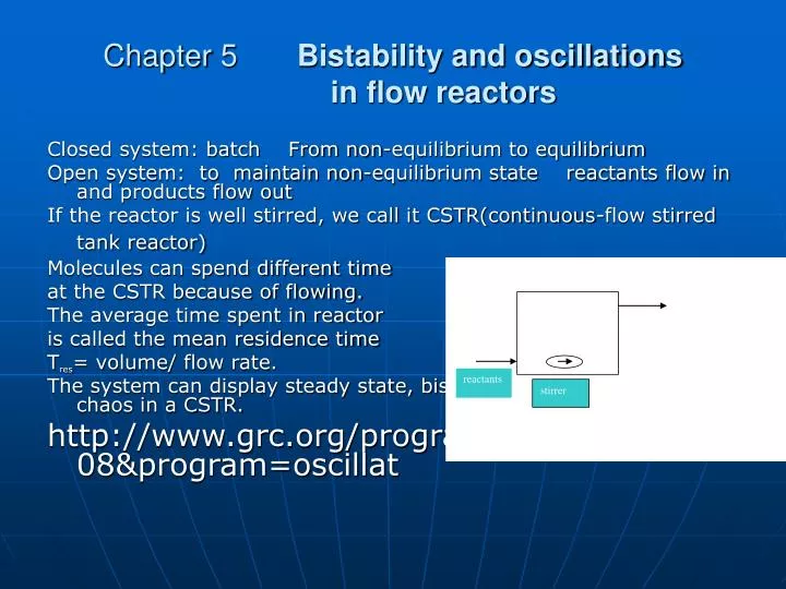
reactants stirrer Chapter 5 Bistability and oscillations in flow reactors Closed system: batch From non-equilibrium to equilibrium Open system: to maintain non-equilibrium state reactants flow in and products flow out If the reactor is well stirred, we call it CSTR(continuous-flow stirred tank reactor) Molecules can spend different time at the CSTR because of flowing. The average time spent in reactor is called the mean residence time Tres= volume/ flow rate. The system can display steady state, bistable state, oscillations, chaos in a CSTR. http://www.grc.org/programs.aspx?year=2008&program=oscillat
reactants stirrer 5.1 Steady state and bistability Example: Iodate - arsenite system IO3-+5I-+3H3AsO3→6 I-+3 H3AsO4 At high flow rate, the concentrations of reactants in a CSTR have not bigger different with the inflow concentrations, this branch is known as flow branch(流动分枝 ). At low flow rate, the system in a CSTR approach the thermodynamic equilibrium , the curve is called thermodynamic branch(热力学分枝) As the flowrate is decreased, the system changes from flow branch to thermodynamic branch Attention: when flowrate change, the system evolve to new state for short(low flowrate) or long (high flow rate)time.
Situations: 1. When changing flowrate up or down, the plot of steady concentrations have only one curve. But during the some region of flowrate, there is a quick change of concentration from one branch to another branch. flow diagram
2. Thermodynamic branch and flow branch overlap as the direction of changing flowrate is opposite. This is phenomena is named bistabilty. Within the region of bistability, the actual state selected depends on not only the parameter but also the operational history. When the flowrate is up or down, the state jumps or fall off in delay. This phenomena is called hysteresis This abrupt changes in compositions is discontinuous responded to the continuous changes in the operating conditions. This is bifurcation.
5.2 Dynamic equations for flow reactors The changes of concentrations in flow reactor result from the net flow and reaction V dA/dt=q(A0-A)+VR dA/dt=k0(A0-A)+R k0=q/V time-1 For iodate-arsenite system IO3-+5I-+6H+=6I-+3H2O R=(Ka1+Ka2[I-])[I-][ IO3-][H+]2Mixed autocalysis d[IO3-]/dt=k0([[IO3-]0-[IO3-])- (Ka1+Ka2[I-])[I-][ IO3-][H+]2
5.3 Steady state solutions: flow diagrams Considering cubic autocatalysis only in iodate-arsenite system d[IO3-]/dt=k0([[IO3-]0-[IO3-])- (Ka1+Ka2[I-])[I-][ IO3-][H+]2 Ka1=0 kc=ka2[H+]2 d[IO3-]/dt=k0([[IO3-]0-[IO3-])- kc [I-]2[ IO3-] conservation of element iodine [I-]0+[IO3-]0=[I-]+[IO3-] a=[IO3-], b=[I-] a0+b0=a+b da/dt=k0(a0-a)-kca(a0+b0-a)2 steady state da/dt=0 a=ass k0(a-ass)-kcass(a0+b0-a)2=0 one or three solution k0(a-ass)=kcass(a0+b0-a)2 ass 与b0 和k0有关
dimensionless equation αss=ass/ao β0=b0/a0 К0=k0/kca02 К0(1-αss)= αss (1+β0-αss)2 F R F=R steady state αss when β0=0.2 1-αss=0 reaction begin , R: curve parabola F: line only one intersection When β0=0.05 three intersections two are stable States are decided by flowrate, [I]0 and history
5.4 Turning points and tangancies Line2,4 are tangential to R,The system is bistable between line2 and line 4 The condition for tangancy F=R dF/dα=dR/dα The stable concentration of α αss±=0.25{3±(1-8β0)0.5} To makeαss real, β0<1/8 The flowrate of points of tangancies( Turning points) Phase diagram
5.5 Nodes and saddles: from bistable states to saddle-node bifurcation In bistable region, there are three steady states, (or three branchs), two are stable, the middle is unstable, How to understand it? For their stability, We use the potential rate=-dα/dt= α(1+β0-α)2-К0(1-α) V=1/2 m Rate2 dV/drate=Rate V=∫Rate d(Rate) V=0.5(1+β0)2α2-2/3(1+β0)α3+1/4α4-К0α(1-1/2α)+V0 At one parameter, Vα1, α3 has the minimum as node, and Vα2 has the maxmum as saddle. when the parameter changes to another, Vα3 merges with Vα2 from node to saddle. This process is called saddle-node bifurcation.
5.6 Designing oscillatory reactions from bistable systems A Nonlinear feedback reaction (quadratic and cubic) + CSTR: only bistability ? Feedback---Clock (batch)------Bistabilty(CSTR) Only a feedback can not bring out oscillations: a+b=2b Degree of Freedom =1 a fixed then b is fixed a+b=a0+b0 B For oscillations, the system must have two degrees of freedom a+b=2b b+c=p C model analysis for CSTR oscillations a+2b3b kc R1 b+cBC k1 k-1 R2 independent variables two b c or bc
assumption: flowing in a b c and bc: no flowing or flowout k1, k-1 small initial concentrations: a0 b0 c0 Concentrations at specific time: a b c, bc=x a0+b0=a+b(k1, k-1 small ) γ=x/a0 γ0=c0/a0 β=b/a0 Non negative feedback ( R2 un-included) Negative included
Inflow rate can be auto-vary and cycled • B(β) big b+cBC BC (γ) rise κ0,effincreases system move automaticallyto right , make B drop at turning point ,and b (β) +cBC (γ) R2 inducing: a+2b=3b Jump to low branch. B small, R2 equilibrium to left, BC (γ) drops, κ0,eff decreases, system moves to left, then B increase to turning point, jump up. So oscillations repeated.
C To understand dynamics from nullclines β nullcline γ nullcline intersection situation have four possibilities. Bistable high β low β oscillations Cross-shapes diagrams Parameter κ0 γ0 ‘ a bistable d oscillations b high β c lowβ near cusp perturbation oscllations or go to stable state If b c display oscillations, then a is the field of birhythmicity and d is the field of complex oscillations or chaos
5.7 Applications of Cross-shaped Diagram Technique Bistable states in CSTR + Negative feedback Autocatalysis + autocatalyst consume,This make the k0,eff change from parameter to variable. Complex dynamics such as oscillations take places. IO3--AsO3- iodide autocatlysis, CIO2- as negative substances IO3-+5I-+6H+=3I2+3H2O I2+ H2O+H3AsO3=2I-+H2AsO4-+2H+ d[I-]/dt=(ka1+Ka2[I-])[I-][IO3-][H+]2 IO3--AsO3-—ClO2- oscillations Landolt reaction + Fe(CN)63- V Gaspar and k. Showalter JPC, 94, 4973
5.8 Complex oscillations and Chaos More than two variables, The system can display complex oscillations, chaos Bifurcation to chaos • Period-doubling quansiperiod
model explaination • A+2B=3B Rate=kcab2 • B=C rate=ktb • a+b+c=a0+b0 Steady state condition P= (k0+kt)2/k0 dynamical flowrate
P= (k0+kt)2/k0 Situation1 : k0>>kt P→k0 Situation2 : k0→0 P→∞ Situation3 : Pmin=4kt Monostability if Pmin> Ftangancy