Download
1 / 76
950 likes | 1.57k Views
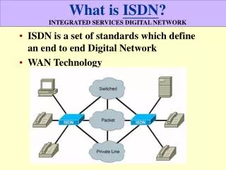
ISDN Integrated Services Digital Network. definition of ISDN evolution to ISDN and beyond ISDN services basic BRA / PRA architecture protocols & signalling. What is ISDN ?. 1. End-to-end digital connectivity 2. Enhanced subscriber signaling

E N D
ISDN Integrated Services Digital Network • definition of ISDN • evolution to ISDN and beyond • ISDN services • basic BRA / PRA architecture • protocols & signalling
What is ISDN ? 1. End-to-end digital connectivity 2. Enhanced subscriber signaling 3. A wide variety of new services (due to 1 and 2) 4. Standardized access interfaces and terminals Idea originated in the 1980’s ISDN is not a “new” network separated from the PSTN. Interworking with “normal” PSTN equipment is very important. interaction is possible ISDN terminal PSTN terminal
Evolution towards ISDN and beyond How does ISDN fit into the telecom network evolution in general? 1. First the network was all-analogue and voice-centric 2. Digital transmission (PDH) in the core network 3. Digital switching at 64 kbit/s 4. SS7 replaces channel associated signalling systems 5. SDH replaces PDH 6. ISDN offers digital technology to end users 7. DSL (primarily ADSL) technology takes over
Evolution history Step 1: All-analogue network (before 1960) Transmission Switching End users
Evolution history Step 2: Digital transmission in the core network (1960 - 1980) PDH transmission systems (2 - 140 Mbit/s)
Evolution history Step 3: Digital switching at 64 kbit/s (1970 - 1990) TDM switching technology
Evolution history Step 4: Common Channel Signalling in the core network (1980 - 2000) SS7
Evolution history Step 5: PDH systems are replaced by SDH systems (1990 ...) SDH transmission systems (155, 620 Mb/s)
Evolution history Step 6: ISDN => digital technology to end users End-to-end digital user data End-to-end digital signalling
Evolution history Step 7: ADSL (for Internet services) + analogue voice High speed Internet access (Back to) traditional voice services Mobile systems
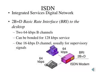
PSTN vs. ISDN user access 300 … 3400 Hz analogue transmission band “poor-performance” subscriber signaling PSTN Basic Rate Access ISDN 2 x 64 kbit/s digital channels (B channels) 16 kbit/s channel for signaling (D channel) 30 x 64 kbit/s digital channels (B channels) 64 kbit/s channel for signaling (D channel) Primary Rate Access ISDN
Digital access: several alternatives ISDN BRA modem ADSL Bit rate (kb/s) 2 x 64 max. 50 much larger Connection fast slow fast setup time Popularity little decreasing great However, large impact on signalling protocols
Telecommunication services ... as defined in ISDN standards Basic telecommunication services Bearer services provide the capability of transmitting signals between network access points. Higher-level functionality of user terminals is not specified. Teleservices provide the full communication capability by means of network functions, terminals, dedicated network elements, etc. Supplementary services A supplementary service modifies or supplements a basic telecommunication service. It cannot be offered to a customer as a stand-alone service.
Services examples • Some typical teleservices • Telephony (normal, high quality) • Telefax (Group 3, Group 4) • Video-telephony • Some typical bearer services • Speech (transparency not guaranteed) • 64 kbit/s unrestricted • 3.1 kHz audio (non-ISDN interworking) • Some typical supplementary services • CLIP / CLIR • Call forwarding / waiting / hold • Charging supplementary services
Basic rate access – user interface Exchange S/T Network Termination U Terminal Adaptor Line Interface Circuit Bi-directional 192 kbit/s 160 kbit/s echo canceling or time compression R Non-ISDN terminal ISDN terminal Exchange Subscriber (premises) network
Primary rate access – user interface Private Branch eXchange (PBX) U Line Termination PBX equipment manufacturer specific solutions Standard 2 Mb/s TDM connection (PDH or SDH) Exchange 64 kb/s D channel in one TDM time slot
Signalling protocols for end-to-end circuit-switched digital connection User interface PSTN Network User interface SS7 Q.931 Q.931 ISUP ISUP Q.931 Q.931 DSS1 DSS1 MTP 3 MTP 3 Q.921 Q.921 MTP 2 MTP 2 Q.921 Q.921 I.430 I.430 MTP 1 MTP 1 I.430 I.430 contains the signalling messages for call control
Layered DSS1 signaling structure DSS1 = Digital Subscriber Signalling system no.1 Layer 1: Bit sequence structure, framing & multiplexing Layer 2: Link control (HDLC-type protocol called LAPD) Layer 3: Signaling messages (application layer) I.430 Q.921 Q.931
Q.931 Call-related messages Call establishment messages: ALERTING CALL PROCEEDING CONNECT CONNECT ACKNOWLEDGE PROGRESS SETUP SETUP ACKNOWLEDGE Call clearing messages: DISCONNECT RELEASE RELEASE COMPLETE Similar functions as ISUP in SS7
Typical content of ISDN Set-up message Called party (user B) number & numbering plan Calling party (user A) number (+ CLIP/CLIR) Bearer capability (64 kbit/s unrestricted, speech, 3.1 kHz audio, packet mode B-channel, packet mode D-channel) Channel identification (B1, B2, or D channel request) Low-layer compatibility (type of bit rate adaptation, type of modem …) High-layer compatibility (teleservice-related issues) Keypad facility Show to B?
Example: Structure of Release message Message type: RELEASESignificance: LocalDirection: Both Info ElementDirection Type Length Protocol Both M 1 discriminator Call referenceBoth M 2- Message typeBoth M 1 CauseBoth O 2-32 Display n u O Signal n u O 2-3 Common header part of message Cause description may require many bytes
Setup of an “old-fashioned” PSTN call User A Exchange A Exchange B User B off-hook SS7 ISUP dial tone B number “rrring” ringing tone user B answers connection ok
Setup of an ISDN call using Q.931 User A Exchange A Exchange B User B Setup off-hook Setup Call proceed SS7 ISUP B1 or B2? Alert “rrring” Alert Connect user B answers Connect connection ok
SS7 Common Channel Signalling System Nr. 7 Bhatnagar, Chapter 4 • CCS vs. CAS • SS7 protocol structure • basic signalling examples • MTP, ISUP and SCCP
History of inter-exchange signalling Before 1970, only channel-associated signalling (CAS) was used. In CAS systems, signalling always occurs in-band (i.e. over voice channels). CAS SS6 = CCIS (common channel interoffice signaling) was widely deployed in North America, but not in Europe (=> concentrating on SS7 instead). CCIS Starting from 1980 (mainly in Europe), CAS was being replaced by SS7. The use of stored program control (SPC) exchanges made this possible. Like CCIS, signalling messages are transmitted over separate signalling channels. Unlike CCIS, SS7 technology is based on protocol stacks. SS7
Channel-associated signalling (CAS) CAS means in-band signalling over voice channels. signalling possible signalling not possible (yet) Exchange Exchange Exchange circuit switched connection CAS has two serious draw-backs: 1) Setting up a circuit switched connection is very slow. 2) Signalling to/from databases is not feasible in practice (setting up a circuit switched connection to the database and then releasing it would be extremely inconvenient).
Common channel signalling (CCS) In practice, CCS = SS7 In Finnish: CCS = yhteiskanavamerkinanto (YKM) signalling possible anywhere anytime Exchange Exchange Database The packet-switched signalling network is separated from circuit switched connections. Consequently: 1) Signalling to/from databases is possible anytime. 2) End-to-end signallingis possible before call setup and also during the conversation phase of a call.
CAS vs. CCS example Tokyo Oulu Exch User A (calling user) Exch Exch User B (called user) Exch Database London 1) Accessing database 2) End-to-end signalling before call setup
Signalling points (SP) in SS7 Every SP is identified by a unique signalling point code Signalling Transfer Point (only related to SS7 network) STP STP Signalling Point (in a database, such as HLR in GSM) SP MAP INAP CAP Application protocols used in SS7 STP Exchange SP Signalling Point (signalling termination in an exchange) ISUP
Protocol layers (”levels”) of SS7 Application protocols TUP ISUP MAP INAP CAP TCAP SCCP routing MTP level 3 MTP level 2 (link-layer protocol) MTP level 1 (64 kbit/s PCM time slot) • MTP - Message Transfer Part • SCCP - Signalling Connection Control Part • UP - User Part AP - Application Part
Application protocols in SS7 • TUP (Telephone User Part) – is being replaced by ISUP • ISUP (ISDN User Part) – for all signalling related to setting up, maintaining, and releasing circuit switched connections • MAP (Mobile User Part) – for transactions between exchanges (MSC, GMSC) and databases (HLR, EIR, AuC) in mobile networks • INAP (Intelligent Network Application Part) for IN applications in fixed networks • CAP (CAMEL Application Part) for extended IN functionality in mobile networks (where MAP is not sufficient ...)
MTP functions • MTP level 1 (signalling data link level): • MTP level 2 (signalling link level): • MTP level 3 (signalling network level): Digital transmission channel (64 kbit/s TDM time slot) HDLC-type frame-based protocol for flow control, error control (using ARQ), and signalling network supervision and maintenance functions. Routing in the signalling network (using OPC,DPC) between SPs with level 4 users (see SIO at level 2).
MTP level 2 frame formats Level 3 signalling message MSU (Message Signal Unit) F CK SIF SIO LI Control F Network: National International User part: TUP ISUP SCCP Network management LSSU (Link Status Signal Unit) F CK SF LI Control F FISU (Fill-In Signal Unit) F CK LI Control F
MTP level 2 frames • MSU (Message Signal Unit): • Contains signalling messages (User Part SIO) • The received frame is MSU if LI > 2 (number of payload octets, payload = SIF or SF) • LSSU (Link Status Signal Unit): • Contains signalling messages for link supervision • The received frame is LSSU if LI = 1 or 2 • FISU (Fill-In Signal Unit): • Can be used to monitor quality of signalling link • The received frame is FISU if LI = 0
Routing information in SS7 message Level 3 signalling message in SIF (Signalling Information Field) Routing label MTP management message: SLC – 4 bit signalling link code SLC OPC DPC MTP SCCP message: SLS – 4 bit signalling link selection SLS OPC DPC
Structure of SS7 ISUP message Level 3 signalling message in SIF (Signalling Information Field) Routing label MTP ISUP message: SLS – 4 bit CIC – 12 bit Max 256 + 1 octets CIC SLS OPC DPC ITU-T structure ANSI => different OpP MaVP MaFP MTC MTC: Message Type Code (name of ISUP message) MaFP: Mandatory Fixed Part (no LI, no parameter names required) MaVP: Mandatory Variable Part (LI, no parameter names required) OpP: Optional Part (LI and parameter names required)
Difference between SLS and CIC SLS defines the signalling link which is used for transfer of signalling information (SLS enables load sharing). CIC defines the circuit (used for a certain circuit switched connection) with which the ISUP message is associated. signalling link STP Exchange Exchange circuit
F CK SIF SIO LI Control F Identification of signalling points (SP) • DPC – Destination Point Code (14 bit 16384 SPs) • Termination point of application transaction • Key information for routing within SS7 network • DPC is inserted by the originating MTP ”user”. • OPC – Originating Point Code (14 bit) • Originating point of application transaction • The ”network indicator” in the SIO octet indicates whether the DPC or OPC is an international, national, or network specific SP identifier.
Same signalling point codes can be reused at different network levels International SPC = 277 SPC = 277 National SPC = 277 Network specific SPC = 277 means different SPs at different network levels
Basic MTP level 3 functions MTP user ISUP SCCP Signalling link MTP level 2 Message distribution Message discrimination Message routing Signalling message handling Signalling network management
ISUP (Integrated Services User Part) Essential for circuit-switching related signalling Generally used in PSTN (i.e., not only for ISDN) Features: Establishment / release of circuit switched connections (basic call control) using link-by-link signalling End-to-end signalling between two exchanges (for this purpose SCCP + ISUP is used) Only for signalling between exchanges (never to/from a stand-alone database). see Bhatnagar, p.77
Example: link-by-link signalling (IAM) Using MTP-level routing table, STP routes message to DPC = 22 STP STP Outgoing MTP MSU: OPC = 22 CIC = 20 DPC = 60 SLS = 2 SL 2 SPC = 15 SPC = 18 SL 4 SL 7 Exchange SPC = 82 Exchange SPC = 22 Exchange SPC = 60 Circuit 20 Circuit 14 Processing in (transit) exchange(s): Received message is sent to user (ISUP) that gives B-number to exchange. Exchange performs number analysis and selects new DPC (60) and CIC (20) Outgoing message: OPC = 82 CIC = 14 DPC = 22 SLS = 4
MTP + ISUP in SS7 The routing capability of MTP is rather limited (routing tables are entirely based on signalling point codes). The ”real” routing through the network(s) during call setup is performed by exchanges on an exchange-to-exchange basis, using the dialed digits and routing tables. exchange ID +358 9 123 4567 Country code National region Subscriber number
Example: link-by-link signalling (non-IAM) Using MTP-level routing table, STP routes message to DPC = 22 Otherwise like link-by-link signalling for IAM message, only difference is here STP STP Outgoing MTP MSU: OPC = 22 CIC = 20 DPC = 60 SLS = 2 SL 2 SPC = 15 SPC = 18 SL 4 SL 7 Exchange SPC = 82 Exchange SPC = 22 Exchange SPC = 60 Circuit 20 Circuit 14 Processing in (transit) exchange(s): Using routing table and incoming routing label, exchange inserts DPC (60) and CIC (20) into outgoing routing label (no number analysis … ) Outgoing message: OPC = 82 CIC = 14 DPC = 22 SLS = 4
Setup of a call using ISUP User A Exchange A Transit exchange Exchange B User B Setup IAM IAM Setup Q.931 Link-by-link signalling (number analysis) Alert ACM ACM Alert Connect ANM ANM Connect Link-by-link signalling (no number analysis) Charging of call starts now
Some basic ISUP messages user A user B IAM – Initial Address Message ACM – Address Complete Message ANM – Answer Message REL – Release Message RLC – Release Complete
Intelligent Network (IN) Concept Operator implements service logic (IN Service) STP SCP Service Control Point (a network element containing the service logic, a database or register) MAP INAP CAP Exchange SSP Service Switching Point (enables service triggering in an exchange) ISUP
SCCP (Signalling Connection Control Part) Essential for non-circuit-switching related signalling • Features: • Essential for end-to-end signalling & database access • Global Title Translation (GTT) for enhanced routing • SubSystem Number (SSN) analysis at destination • 4 Transport Service Classes OSI Layer 3 functionality OSI Layer 4 functionality
SS7 connection setup using SCCP Signalling connection, not circuit switched connection (= call), ”setup” => several higher level signalling transactions over the same connection possible User (Ap.) User applications User (Ap.) User (Ap.) User (Ap.) SCCP SCCP GT translation SCCP SSN analysis MTP MTP MTP SSP STP SCP
Global title translation (GTT) Global title translation (GTT) is required when the originating exchange (SSP) knows the ”global title” instead of the point code of the database (SCP). Network node with GTT capability SSP STP SCP Global title (GT) example: Global title translation Find SCP using GT (0800 number) Change GT (0800 number) into DPC + SSN