Download
1 / 36
360 likes | 592 Views
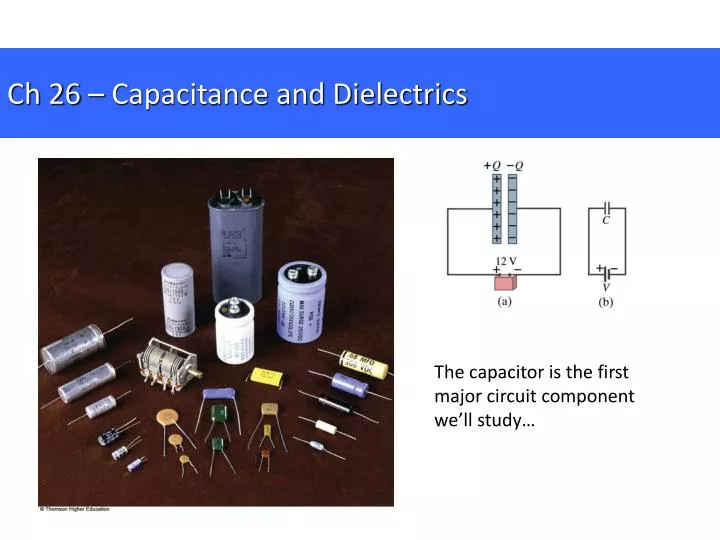
Ch 26 – Capacitance and Dielectrics. The capacitor is the first major circuit component we’ll study…. Ch 26.1 – Capacitance. All conductors display some degree of capacitance . Usually, the term “ capacitor ” refers to two separate pieces of metal acting together.

E N D
Ch 26 – Capacitance and Dielectrics The capacitor is the first major circuit component we’ll study…
Ch 26.1 – Capacitance All conductors display some degree of capacitance. Usually, the term “capacitor” refers to two separate pieces of metal acting together. Each piece of metal is referred to as a plate.
Ch 26.1 – Capacitance Electric field lines generated by a real parallel plate capacitor. Notice, the field is essentially uniform between the plates.
Charging a capacitor: Fig 26-4b, p.800
Charging a capacitor: Chemical potential energy maintains charge separation in the battery the battery generates an E-field. Fig 26-4b, p.800
Charging a capacitor: Chemical potential energy maintains charge separation in the battery the battery generates an E-field. The battery’s E-field accelerates charges in the wires. Electrons flow off the orange plate and toward the blue plate. Fig 26-4b, p.800
Charging a capacitor: Chemical potential energy maintains charge separation in the battery the battery generates an E-field. The battery’s E-field accelerates charges in the wires. Electrons flow off the orange plate and toward the blue plate. Now, there is a charge imbalance across the capacitor’s plates. So… what must exist in between the plates of the capacitor? … an electric field. Fig 26-4b, p.800
Charging a capacitor: Chemical potential energy maintains charge separation in the battery the battery generates an E-field. The battery’s E-field accelerates charges in the wires. Electrons flow off the orange plate and toward the blue plate. Now, there is a charge imbalance across the capacitor’s plates. So… what must exist in between the plates of the capacitor? … an electric field. Charge continues to flow until the E-field in the capacitor is strong enough to cancel the E-field in the battery. Fig 26-4b, p.800
Ch 26.1 – Capacitance A capacitor stores electrical potential energy by virtue of separating charges. The stored energy is “in” the capacitor’s E-field. Based on geometry and materials, some capacitors are better at storing energy than others.
Ch 26.1 – Capacitance Called a capacitor because the device has some “capacity” to store electrical charge, given a particular applied potential difference (voltage). The ability of a capacitor to store charge given a certain applied voltage is called its “capacitance.”
Ch 26.1 – Capacitance – factors affecting capacitance • Size of the capacitor (A, d) • Geometric arrangement • Plates • Cylinders • Material between conductors • Air • Paper • Wax
Ch 26.1 – Capacitance The “capacitance,” C, of a capacitor is the ratio of the charge on either conductor to the potential difference between the conductors:
Ch 26.1 – Capacitance Units: 1 F = 1 C/V The “farad” magnitude of charge on one plate voltage across the capacitor
EG – Definition of Capacitance • How much charge is on each plate of a 4.00μF capacitor when it is connected to a 12.0-V battery? • If this same capacitor is connected to a 1.50-V battery, what charge is stored?
Ch 26.2 – Parallel Plate Capacitors - one plate has +Q, the other -Q - for each plate σ = Q/A
Ch 26.2 – Parallel Plate Capacitors - one plate has +Q, the other -Q - for each plate σ = Q/A - Gauss’s Law the E-field just outside one of the plates
Ch 26.2 – Parallel Plate Capacitors Working backwards from the uniform E-field, the magnitude of the voltage between the plates is
Ch 26.2 – Parallel Plate Capacitors Working backwards from the uniform E-field, the magnitude of the voltage between the plates is Capacitance of parallel plate capacitor But:
Ch 26.2 – Parallel Plate Capacitors Capacitance of parallel plate capacitor Capacitance of a parallel-plate capacitor is directly proportional to the area of the plates and inversely proportional to the distance between the plates. Think about:
EG 26.1 – Cylindrical Capacitor A solid, cylindrical conductor of radius a and charge Q is coaxial with a cylindrical shell of negligible thickness, radius b>a, and charge –Q. Find the capacitance of this capacitor if its length is l.
EG 26.2 – Spherical Capacitor A spherical capacitor consists of a spherical conducting shell of radius b and charge –Q concentric with a smaller conducting sphere of radius a and charge Q. Find the capacitance of this device.
Ch 26.3 – Combinations of Capacitors Capacitors are intentionally used in circuits to alter the rates of change of voltages. Capacitors can be hooked up in two ways: - networked in parallel - networked in series
Ch 26.3 – Combinations of Capacitors – parallel network • Connecting wires are conductors in electrostatic equilibrium Ein =0 • Left plates at same electric potential as the positive terminal of the battery. • Right plates at same electric potential as the negative terminal of the battery. • Therefore, all capacitors in a parallel network experience the same potential difference, in this case, ΔV. ΔV1=ΔV2=ΔV ΔV
Ch 26.3 – Combinations of Capacitors – parallel network The individual voltages across parallel capacitors are equal, and they are equal to the voltage applied across the network. ΔV1=ΔV2=ΔV ΔV
Ch 26.3 – Combinations of Capacitors – parallel network • When battery is attached to circuit capacitors quickly reach maximum charge, Q1 and Q2. • total charge stored by the circuit is Qtot = Q1 + Q2. • So, for a given applied voltage, this network has some “capacity” to store charge. • In other words, the network itself can be thought of as a single capacitor, even though it has many components. ΔV1=ΔV2=ΔV ΔV
Ch 26.3 – Combinations of Capacitors – parallel network • Let’s replace the two-capacitor network with a single equivalent capacitor that has capacitance Ceq. • Based on the definition of capacitance, Ceq = Qtot/ΔV. • Qtot= CeqΔV • But, Qtot = Q1 + Q2, so CeqΔV = C1ΔV1+ C2ΔV2 • In conclusion: Ceq= C1+ C2 (parallel network) ΔV1=ΔV2=ΔV ΔV
Ch 26.3 – Combinations of Capacitors – parallel network • In general, • Ceq= C1+ C2+… (parallel network) The equivalent capacitance of a parallel network is: -the algebraic sum of the individual capacitances -greater than any of the individual capacitances composing the network Ceq Qtot ΔV
Ch 26.3 – Combinations of Capacitors – series network • Left plate of capacitor 1 is at same potential as positive terminal of the battery. • Right plate of capacitor 2 is at same potential as negative terminal of battery. • “Middle leg” has no net charge. ΔV
Ch 26.3 – Combinations of Capacitors – series network • When battery is connected, electrons flow off the left plate of C1 and onto the right plate of C2. • Electrons accumulate on right plate of C2, establishing an electric field. • E-field forces electrons off the left plate of C2 and onto right plate of C1. • All right plates end up with –Q, and all left plates end up with +Q. ΔV
Ch 26.3 – Combinations of Capacitors – series network ΔV2 ΔV1 • In other words, the magnitude of charge on all the plates is equal. • Q1 = Q2 = Q • Additionally, once the circuit reaches electrostatic equilibrium, the voltage across the network must cancel the battery’s voltage. • ΔVtot = ΔV1 + ΔV2 { { ΔV
Ch 26.3 – Combinations of Capacitors – series network ΔV2 ΔV1 • This series network has some ability to store charge given an applied voltage, ie., it has some capacitance • In other words, even though the network has multiple components, it can be modeled using a single equivalent capacitor. • Lets build the same circuit using a single equivalent capacitor. { { ΔV
Ch 26.3 – Combinations of Capacitors – series network ΔV2 ΔV1 Q1 = Q2 = Q (previous result) ΔVtot = ΔV1 + ΔV2 (previous result) From the definition of capacitance, ΔVtot = Q/Ceq Substituting for Δ Vtot, Q/Ceq = Q1/C1 + Q2/C2 Cancelling Q, 1/Ceq = 1/C1 + 1/C2 (series combination) { { ΔV
Ch 26.3 – Combinations of Capacitors – series network Q1 = Q2 = Q (previous result) ΔVtot = ΔV1 + ΔV2 (previous result) From the definition of capacitance, ΔVtot = Q/Ceq Substituting for Δ Vtot, Q/Ceq = Q1/C1 + Q2/C2 Cancelling Q, 1/Ceq = 1/C1 + 1/C2 (series combination) ΔV { Ceq Q ΔV
Ch 26.3 – Combinations of Capacitors – series network • In general, • 1/Ceq = 1/C1 + 1/C2 +… (series combination) • The inverse of the equivalent capacitance is the algebraic sum of the inverses of the individual capacitances. • The equivalent capacitance is always less than any individual capacitances in the network. ΔV { Ceq Q ΔV
EG 26.3 – Equivalent Capacitance Find the equivalent capacitance between a and b for the combination of capacitors shown. All capacitances are in microfarads.

![G5 - ELECTRICAL PRINCIPLES [3 exam questions - 3 groups]](https://cdn0.slideserve.com/382273/g5-electrical-principles-3-exam-questions-3-groups-dt.jpg)