Download
1 / 14
140 likes | 232 Views
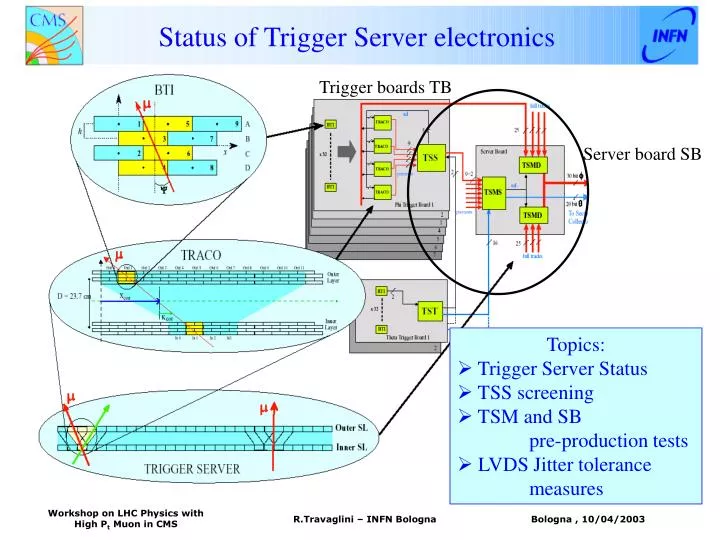
Status of Trigger Server electronics. Trigger boards TB. Server board SB. Topics: Trigger Server Status TSS screening TSM and SB pre-production tests LVDS Jitter tolerance measures. LVDS to Sector Collector. ……. Link board. Server Board. Chamber Minicrate. Control

E N D
Status of Trigger Server electronics Trigger boards TB Server board SB Topics: • Trigger Server Status • TSS screening • TSM and SB pre-production tests • LVDS Jitter tolerance measures R.Travaglini – INFN Bologna
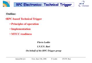
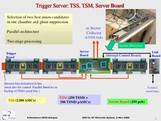
LVDS to Sector Collector …… Link board Server Board Chamber Minicrate Control serial line Trigger Server – Status update “backplane” bus • TSS (1200 ASIC, Alcatel 0.5 mm): • - full production already delivered • currently: screening of 1200 working devices ready to start • TSM • (250 TSMS + 500 TSMD pASIC, Actel, 0.35 mm): • 1000 device (to be fused) in hands • - Final Prototype succesfully tested! • 1 month to fuse all chips • (ext firm already contacted): wait for pre-production tests of the Server Board (End Apr.) • Server Board : • pre-production delivered in March. 03 (5 SB) • 2 SB succesfully tested ! • Pre-series production will start soon (beginning of May) -> to provide 35 SB for ’03 minicrate production • tender for full production going on R.Travaglini – INFN Bologna
TSS Screening – HW system Screening will be performed in Bologna with the test jig setup for prototypes Piggy board mounted on a Pattern unit emulating Traco input and receiving output TSS Asic Alcatel 0.5 mm CMOS Product by Europractice R.Travaglini – INFN Bologna
TSS Screening – SW system SW developed in Visual C++, fully automatic *) interfaces Power supply and clock generator through GPIB protocol *) interfaces mySQL database for bookeeping • Full test: • Bonding check • Running test • (different conf, • Clock frequency and • Voltage supply) • Monitor and control logic check • (Jtag and Parallel access) • Spying and Test features • (snap and test reg.s) • Power consumption • continuously monitored R.Travaglini – INFN Bologna
Delivery consists of 2700 chips Process yield 70% Package yield 90% (conservative estimate) To have 1200 TSS working We need to test ~ 2000 chip 2 min/chip 4 weeks ! With a working time of 4 hour/day TSS Screening – System performance Performances of the test system: Bonding check ( < 1 s) Test sorting in different setups with 106 patterns (~16 s @ 60 Kevt/s) Test monitoring and control logic ( ~ 5 s) Bookeeping into the database R.Travaglini – INFN Bologna
Server Board – Pre-production 20.6 cm PCB 16 layers ! Front side TSM side 9.5 cm National serializer 10-to-1 DS92LV1021 TSMS TSMDs Reminder: TSM is implemented with 3 pASIC Actel A54SX32 0.35 mm CMOS NB: Backside contains most of the control logic electronics for the minicrate R.Travaglini – INFN Bologna
Server Board – Test System Pattern Units Crate VME Vme board with CPU Pentium II 80 bits @ 40 MHz Rs232 PC serial port Server Board Trigger Link Rx 232 bits @ 40 MHz 232 bits @ 40 MHz LVDS link – data serialized @ 480 MHz 2 copper cables FTP class 6– 40 m Adapter Board R.Travaglini – INFN Bologna
Server Board – Test Setup Server Board Adapter Board Trigger Link Rx R.Travaglini – INFN Bologna
Server Board – Software for tests Developed under WinNT with Visual C++ • SW controls all test options: • Generates, transmits and receives pattern • Checks output with emulation • Finds better setup conditions • Provides monitoring and configuring Clock phase (input) Good working condition! Clock phase (output) SW to use for full SB production test. R.Travaglini – INFN Bologna
TSM design – a reminder… TSM system is the bottleneck of the trigger electronics on chamber. It is segmented on 3 pASICs with partially redundant functionalities: • Two main working modes: • Normal mode (all pASICS work properly) • Backup mode (one or two pASICs in failure) R.Travaglini – INFN Bologna
TSM algorithm – another reminder.. Remember: TRACO sends 2 tracks belonging to the same trigger events in 2 consecutive BXs TS task : to sort two best tracks in two consecutive BXs Normal mode: implemented by sorting 1 track out of 6 for BX Backup mode: each half chamber sorts 2 tracks independently in two BXs, by means of a “quick” sorting (quality bits are involved) Main features (enabled in default , can be switched off): Recovery of “good” track eventually found at the previous BX (called carry ) Ghost rejection Recovery of “good” tracks in overlapped events (i.e.pile-up between tracks from events in consecutive BXs) R.Travaglini – INFN Bologna
TSM and SB – Test Status • Server Board Tests Summary (2 boards fully tested): • Board layout was checked and approved for production. • Signals transmission from Pattern Units has been successfully checked! (N.B: it has the same characteristics of transmission from Trigger Boards) • TSM monitoring and configuring works fine! • TSM output tests with LVDS transmission through 40 m cables has been performed. • TSM Algorithm Tests Summary: • First test: About 1000 “surgical” input patterns have been initially used. These “surgical” patterns, developed during the chip design and simulation, thoroughly check all functionalities, in different configurations also. • Second test: About 109 random input patterns have been submitted with different configurations in long tests periods (3-4 days) to find bugs and check stability and performances Results: -TSM and SB work as expected up to 44 MHz of clock frequency and transmitting output through cables long up to 40 m. R.Travaglini – INFN Bologna
LVDS Trigger Link DTTF ( in USC55 ) Opto-Link Sector Collector Board Balcony Sector Collector VME Crate MB 4 TSM MB 3 TSM “Ethernet” cables ( up to ~40m ) CLASS 6 FTP Z0= 100 MB 2 TSM MB 1 TSM R.Travaglini – INFN Bologna
Jitter Measurements • Jitter Tolerance measured in Bologna • Stand-alone LVDS transmission • system equipped as the final • trigger link system • Clock Jitter generator • Maximum Jitter tolerated from National • Serializer LVDS in worst conditions with • Cable of 40 m lengths • => RMS = 80 ps • Jitter Tolerance measured in Legnaro • TTCex driven by TTCvi • TTCoc inserted • (Optical input power = -20dBm) • TTCrx in MC sends clock on LVDS ser. • No Broadcast command • Measured : RMS = 26 ps R.Travaglini – INFN Bologna