Download
1 / 12
120 likes | 203 Views
Guide to STM Amplifier Sensitivity. The pre-amp converts the tunnelling current to a voltage that is used by the feedback circuit. Pre-amp sensitivity settings are awkward but are important to the proper function of the STM. . There are three things you need to be sure of:

E N D
The pre-amp converts the tunnelling current to a voltage that is used by the feedback circuit. Pre-amp sensitivity settings are awkward but are important to the proper function of the STM. • There are three things you need to be sure of: • The pre-amp sensitivity. • The position of the gain switch on the scanner. • The software Conversion Coefficient (nA/V) (found in View Setup). • Hardware and software need to be consistent for the STM to work properly or the system can become unstable or simply output data that is not the same as the settings in the software.
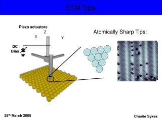
1. Pre-amp Sensitivity • There are three pre-amp types that are differentiated by their maximum sensitivity: • 0.1 nA/V • 1 nA/V • 10 nA/V 1. • The fool-proof way to find out which you have: • Remove the four screws on the tip holder piece. • Carefully pull out the pre-amp module. Do not pull on the cable. • Each sensitivity is identified by the colour of the pre-amp circuit board: • 0.1 nA/V -> Green • 1 nA/V -> Blue • 10 nA/V -> Red 2.
2. Gain Switch The switch on the top of the STM scanner determines the conversion ratio of the current to a maximum voltage of 10V. There are two gain settings, ×1 and ×10. ×10 ×1 nA V 10 9 8 7 6 5 4 3 2 1 0 10 9 8 7 6 5 4 3 2 1 0 Example: If we use a 1 nA/V pre-amp (blue board) and the gain switch is set to ×1 (to the right), the output sensitivity will be 1 nA/V. The pre-amp will convert 1 nA to 1 V. If the gain switch is set to the left (current to voltage conversion of ×10), every nA that tunnels is converted to 10V. This means the sensitivity is 0.1 nA/V. A general rule is that the switch in the right side position will give the maximum sensitivity - 1 nA/V as opposed to 0.1 nA/V (1/10th of the right position).
2. Gain Switch The switch on the top of the STM scanner determines the conversion ratio of the current to a maximum voltage of 10V. There are two gain settings, ×1 and ×10. ×10 ×1 nA V 1 0.9 0.8 0.7 0.6 0.5 0.4 0.3 0.2 0.1 0 10 9 8 7 6 5 4 3 2 1 0 Example: If we use a 1 nA/V pre-amp (blue board) and the gain switch is set to ×1 (to the right), the output sensitivity will be 1 nA/V. The pre-amp will convert 1 nA to 1 V. If the gain switch is set to the left (current to voltage conversion of ×10), every nA that tunnels is converted to 10V. This means the sensitivity is 0.1 nA/V. A general rule is that the switch in the right side position will give the maximum sensitivity - 1 nA/V as opposed to 0.1 nA/V (1/10th of the right position).
Preamp Summary The switch on the top of the STM scanner determines the conversion ratio of the current to the voltage. There are two gain settings, ×1 and ×10. ×10 ×1 0.01 nA/V 0.1 nA/V 1 nA/V 10 nA/V ×10 ×1 GREEN BOARD ×10 ×1 BLUE BOARD ×10 ×1 RED BOARD
Current to Voltage Conversion The gain switch simply changes the resistance applied to the current. Applying Ohm’s law, R = V/I, to the previous example (blue board): ×10 ×1 For a sensitivity of 0.1 nA/V (gain switch on left), I = 10-8 and V = 1: V/I = 1/10-8 = 108Ω = 100 MΩ For a sensitivity 1 nA/V (gain switch on right), I = 10-9 and V = 1: V/I = 1/10-9 = 109Ω = 1 GΩ Higher sensitivity results from higher resistance.
3. Conversion Coefficient The conversion coefficient (the sensitivity), known from the pre-amp board colour and the gain switch position, should be entered into the software in View Setup: Blue board, switch set to right. (or red board, switch set to left)
3. Conversion Coefficient An incorrect conversion coefficient can cause problems: “…if you have a 1 nA/V amplifier on the right side switch setting, but the software thinks it is 10 nA/V and your STM setpoint is 0.1 nA, the system will engage when 0.01 nA of current is actually passing through the amplifier. That’s going to mean your tip is much farther away from the surface than your really want.” You’re essentially telling the software the signal is ten times greater than it actually is so currents are multiplied up. Particularly important for break junction experiments. To far away and the junction might not be made, even if the maximum current of the scanner is reached.
Checks It is very important then to get this right, and is useful to check the conversion coefficient when you take over the STM or change the scanner and calibration file. I have written the pre-amp board sensitivity on the two (different) STM3 scanners. Gain switches are normally on the right so only the conversion coefficient in software should change. Some calibration files are wrong!
Fail to do the checks and... 1. Your tip-sample separation could be very small. If your current is too high (such as how I had mine) then a 1000-datapoint plot will not give you the resolution you need to pick out your single molecule conductance: 0.075 nA 0.75 nA @0.6V I/V = 1.25 nS = 1.61 × 10⁻⁵ G0 0.67 nA 6.7 nA
Or... 2. Your tip-sample separation could be very large. If your current is too low then plateau detection is limited, however, plateaus at lower conductances come into view (?). 0.5 nA 0.05 nA @0.6V I/V = 0.0833 nS = 1.076 × 10⁻⁶ G0 0.05 nA normally crowded out by low end noise. New plateaus at lower SMC?