Download
1 / 45
550 likes | 1.36k Views
Industrial Product & System Automation Division Product service department. TECO Servo Drives JSDA Series parameter description. CONTENTS. User setting function Operator Panel Wiring diagram Alarm messages Parameter description. User setting function.

E N D
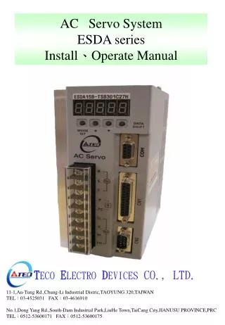
Industrial Product & System Automation Division Product service department TECO Servo Drives JSDA Series parameter description
CONTENTS • User setting function • Operator Panel • Wiring diagram • Alarm messages • Parameter description
User setting function • Parameters can be set or altered using the integrated keypad or the PC Link software. • Keypad includes a 5 digit display.
Operator Panel FIVE 7-SEGMENT LED DISPLAY CHARGE LED POWER LED
Operator panel After Power up 9 groups of parameter could be selected by the “MODE” key on the keypad. AL-xx Cn0xx Alarm History System Control Tn1xx dn-xx Torque Diagnostics Sn2xx Un-xx Speed Status Display Pn3xx Hn5xx qn4xx Quick Setup Position Multi-function Inputs/Outputs
Parameter description xx :- item number of the parameter groups
Control Mode Codes Symbol definition for of Parameters
Diagnosis Parameter • User can use diagnosis parameter to get all information of current system. The description are as below:
Alarm status display When a servo drive fault occurs,display will show and Alarm Code such as Fault Status Display: For AL 05 for example refer to the Alarm list.AL 05 indicates encoder feedback signal error. Servo drive also provides a fault record history as listed below:-
Moters rotate direction(Motor Load) Control System Parameter -2
Parameter • Name & Function • Default • Unit • Setting • Range • Control • Mode • ★Cn009 • CW/CCW Drive forbid mode • 0 • X • 0 • │ • 2 • ALL • Setting • Explanation • 0 • Servo Motor decelerate to stop through default torque limit(Cn010、Cn011). • 1 • Servo Motor decelerate to stop through default torque limit (Cn010、Cn011),and usig the dynamic brake (priority to Cn008) • 2 • Servo Motor decelerate to stop through ±300% Torque flimit. • Cn010 • CCW direction torque Command limit value • 100 • % • 0 • │ • 300 • ALL • Ex: If 2 times of rated Torque be CCW Torque Command limit, then set Cn001=200. • Cn011 • CW Torque Command limit value • -100 • % • -300 • │ • 0 • ALL • Ex: If 2 times of rated Torque be CW Torque Command limit, then set Cn011=-200. • Cn012 • Setting of the power of ExternalRe-generationresister • 60 • W • 0 • │ • 10000 • ALL • According to 5-6-7 to choose the resister and set it’s power value at Cn012 • ★Cn013 • Frequency of resonance restrain Filter • 0 • Hz • 0 • │ • 1000 • Pi • Pe • S • Please enter the resonance frequency of vibration in Cn013, if the noise or vibration must be eliminated. • ★Cn014 • Quality-Factors of the Resonance restrain Filter • 7 • X • 1 • │ • 100 • Pi • Pe • S • Adjusting the range of the frequency, lower the number of Cn014 is, wider the restrained range of frequency is. Control System Parameter -5
Parameter Name & Function Default Unit Setting Range Control Mode • Cn026 Rigidity Setting 4 X 1 │ A Pi Pe S When using the auto-increase adjustment function, Rigidity Range should be set first in accordance with all appliance. The Rigidity Setting ranges in all kinds of appliance follow as below: Setting Explanation Position Loop Gain Pn310 [1/s] Speed Loop Gain Sn211 [Hz] Speed Loop Integration-Time Constant Sn212 [x0.2msec] 1 15 15 300 2 20 20 225 3 30 30 150 4 40 40 100 5 60 60 75 6 85 85 50 7 120 120 40 8 160 160 30 9 200 200 25 A 250 250 20 Control System Parameter -9
Parameter Name & Function Default Unit Setting Range Control Mode Pn304 Electronic Gear Ratio Numerator 3 1 X 1 │ 50000 Pi Pe • Use input contacts GN1 & GN2 to switch 4 groups of Electronic Gear Ratio Numerator. When using the Numerator 3, the statue of the input-contacts GN1 & GN2 are: • P.S.:Input-contact-statue 1 stands for Switch ON, 0 stands for SwitchOFF. If setting high potential action or low potential action, please refer to 5-6-1 to set. Input-contact GN2 Input-contact GN1 1 0 Pn305 Electronic Gear Ratio Numerator 4 1 X 1 │ 50000 Pi Pe • Use input contacts GN1 & GN2 to switch 4 groups of Electronic Gear Ratio Numerator. When using the Numerator 4, the statue of the input-contacts GN1 & GN2 are: • P.S.:Input-contact-statue 1 stands for Switch ON, 0 stands for SwitchOFF. If setting high potential action or low potential action, please refer to 5-6-1 to set. Input-contact GN2 Input-contact GN1 1 1 ★Pn306 Electronic Gear Ratio Denominator 1 X 1 │ 50000 Pi Pe • Set Pn306(Electronic Gear Ratio Denominator) to match input-contacts GN1 and GN2’s electronic gear ratio numerator. And the final electroni gear ratio must match the condition below, otherwise, it can not normally operate Pn307 In Position band Value 10 pulse 0 │ 50000 Pi Pe When the Position error value is lower then Pn307’s pulse number(Position Fixed Judgement Value), output-contact INP carry into effect. Position Control Parameter -2
Parameter • Name & Function • Default • Unit • Setting • Range • Control • Mode • Pn308 • Positive-maximum Position Error Judgment Value • 50000 • pulse • 0 • │ • 50000 • Pi • Pe • When the Position error value is higher then Pn308’s pulse number (Positive maximum position error judgment value), this device give us AL-11(Position error value alert) • Pn309 • Negative Maximum Position Error Judgment Value • 50000 • pulse • 0 • │ • 50000 • Pi • Pe • When the Position error value is higher then Pn309’s pulse number (Negative maximum position error judgment value), this device give us AL-11(Position error value alert) Pn310 Position Loop Gain 1 40 1 │ 450 Pi Pe • Under the situation that there are no vibration or noise of machinery system. Increasing the position loop gain value can speed up reaction and shorten the time of fixing position. Generally, the position loop bandwidth can not higher then speed loop bandwidth. Here is the suggested formula below: Pn311 Position Loop Gain 2 40 1/s 1 │ 450 Pi Pe Please refer to Pn310 Pn312 Position Loop Feed Forward Gain 0 % 0 │ 100 Pi Pe It can reduce the follow up error of position control and speed up the reaction. If the feed forward gain is too over, it might cause speed overshooting and re-ON/OFF of output contact INP(Position Complete signal). ★Pn313 Position Command : one Time smooth ac/decelerational Time-Constant 10 msec 0 │ 10000 Pi Pe It cause the position pulse command of original constant frequency smooth. Position Command-one time smooth ac/decelerational Time-Constant stands for the Time-Constant stands for the time in which position pulse command frequency starts from 0 to 63.2%. Position Control Parameter -3
★Pn314 • Position Command direction definition (Load Side) 1 X 0 │ 1 Pi Pe Setting Explanation 0 (CW) 1 (CCW) Pn315 Pulse Error amount Eliminate Mode 0 X 0 │ 2 Pe Setting Explanation 0 When CLR act, it eliminates the Pulse-error-amount. 1 When CLR works, it cencels the position command to interrupt Motor’s Rotate, reset machinery origin and clean pulse error amount. Pi Pe 2 When CLR works, it cencels position command to interrupt Motor’s Rotate and clean pulse error amount. Pi ★Pn316 To Pn-317 Internal Position Command Mode Setting the 16 P to P internal Position Command Position Control Parameter -4 0 0 │ 1 Pi
Parameter Name & Function Default Unit Setting Range Control Mode • Pn365.0 After Zero Point Return operates, the Setting of ZeroPoint Direction Searching and Zero Reference. 0 X 0 │ 5 Pi Pe • Pn365.1 After finding Origin Reference Point, the Settings of Move Method of searching machinery orign 0 X 0 │ 2 • Pn365.2 Origin Return Mode Setting 0 X 0 │ 2 • Pn365.3 The Setting of Stop after Finding Machinery Orgin 0 X 0 │ 1 Pn366 Machine Zero Point Return – 1st stage – High Speed 100 rpm 0 │ 2000 Pi Pe Pn367 Machine Zero Point Return – 2nd stage – Low Speed 50 rpm 0 │ 500 Pi Pe Pn368 Machine Zero Point Return Off-Set Rotate Number 0 rev -30000 │ 30000 Pi Pe Pn369 Zero Point Return OFF-Set Pulse Number 0 pulse -32767 │ 32767 Pi Pe Position Control Parameter -5


![Experiment 1 Id Title Description Institution [Parameter Sets…]](https://cdn2.slideserve.com/3773607/slide1-dt.jpg)