Download
1 / 36
380 likes | 413 Views
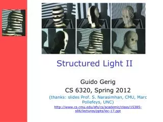
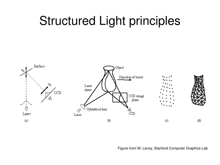
Structured Light principles. Figure from M. Levoy, Stanford Computer Graphics Lab. Coding structured light. Why coding structured light. Point lighting - O(n ² ) “Line” lighting - O(n) Coded light - O(log n)*. * Log base depends on code base.

E N D
Structured Light principles Figure from M. Levoy, Stanford Computer Graphics Lab
Why coding structured light • Point lighting - O(n²) • “Line” lighting - O(n) • Coded light - O(log n)* * Log base depends on code base By reducing the number of captured images we reduce the requirements on processing power and storage.
Pipeline • Calibrate a pair camera/projector. • Capture images of the object with projected patterns. • Process images in order to correlate camera and projector pixels : • Pattern detection. • Decoding projector position. • Triangulate to recover depth.
Our Goal • How to correlate camera and projector pixels? • Different codes gives us several possibilities to solve correlation problem. • We are going to show you an overview of many different approaches.
CSL research • Early approaches (the 80’s) • Structuring the problem (the 90’s) • New Taxonomy • Recent trends • Going back to colors
Main ideas Structured Light Codes can be classified observing the restrictions imposed on objects to be scanned: • Temporal Coherence. • Spatial Coherence. • Reflectance restrictions.
Temporal Coherence • Coding in more than one frame. • Does not allow movement. • Results in simple codes that are as less restrictive as possible regarding reflectivity.
Spatial Coherence • Coding in a single frame. • Spatial Coherence can be local or global. • The minimum number of pixels used to identify the projected code defines the accuracy of details to be recovered in the scene.
Binary spatial coding http://cmp.felk.cvut.cz/cmp/demos/RangeAcquisition.html
Introducing color in coding • Allowing colors in coding is the same as augmenting code basis. This gives us more words with the same length. • If the scene changes the color of projected light, then information can be lost. • Reflectivity restrictions (neutral scene colors) have to be imposed to guarantee the correct decoding.
Local spatial Coherence http://www.mri.jhu.edu/~cozturk/sl.html • Medical Imaging LaboratoryDepartments of Biomedical Engineering and RadiologyJohns Hopkins University School of MedicineBaltimore, MD 21205
6 different colors used to produce sequences of 3 without repetition Images from: Tim Monks, University of Southampton
Rainbow Pattern Assumes that the scene does not change the color of projected light http://cmp.felk.cvut.cz/cmp/demos/RangeAcquisition.html Examples: http://eia.udg.es/~jpages/examples/examples.html
Slide 1 (column 1) Slide 2 (column 2) Ghost boundary Boundary Coding 01 11 The graph edges correspond to the stripe transition code. 10 The maximal code results from an Eulerian path on graph. Obs.: 2 frames of Gray code gives us 4 stripes. In this case we have 10. 00 edge 00 01 Slide 1 Slide 2
Comments • It scans moving objects. • It is designed to acquire geometry in real-time. • Some textures can produce false transitions leading to decoding errors. • It does not acquire texture. Mostrar vídeo
Noisy transmission channel • There is a natural analogy between coded structured light and a digital communication system. • The camera is recieving the signal transmitted through object by the projector. • Structure of coding: • Number of slides • Number of characters used in as “alphabet” • Size of the “words” • Neighborhood considered
Designing codes Goal: design a light pattern to acquire depth information with minimum number of frames without restricting the object to be scanned (impose only minimal constraints on reflectivity, temporal coherence and spatial coherence.) • What is Minimal? • Temporal Coherence: 2 frames. • Spatial Coherence: 2 pixels. • Reflectivity restrictions: allow non neutral objects to be scanned without loosing information.
Processing images • To recover coded information a pattern detection procedure has to be carried out on captured images. • The precision of pattern detection is crucial to the accuracy of resulting range data. • Shadow areas also have to be detected. • Edge detection • Stripes transitions produce edges on camera images. • Transitions can be detected with sub-pixel precision. • Projecting positive and negative slides is a robust way to recover edges.
Revisiting Colors • Taking advantage of successively projecting positive and negative slides, reflectivity restrictions can be eliminated. • To solve the problem of allowing ghost boundaries we have to augment the basis of code, that is, allowing colors.
Recovering colored codes • u is the ambient light • r is the local intensity transfer factor mainly determined by local surface properties • p is the projected intensity for each channel Negative slide Positive slide
(b,s)-BCSL • Augment basis of Rusinkiewicz code eliminating ghost boundaries. • We proposed a coding scheme that generates a boundary stripe codes with a number b of colors in s slides, it is called (b,s)-BCSL.
16th transition Decoding table
…after processing: Mostrar Vídeo
How to reconstruct the entire object? • Capturing images from many different points of view. • The resultant clouds of points have to be aligned to be unified. • The clouds of points can be processed to become a mesh.
Projected pattern changing object’s position From: Medical Imaging LaboratoryDepartments of Biomedical Engineering and RadiologyJohns Hopkins University School of MedicineBaltimore, MD 21205