Download
1 / 116
1.27k likes | 1.62k Views
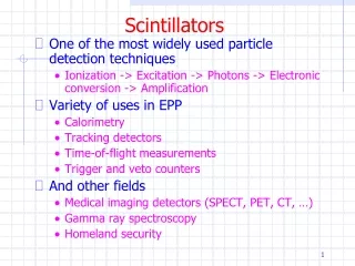
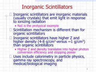
Inorganic Scintillators. Inorganic scintillators are inorganic materials (usually crystals) that emit light in response to ionizing radiation NaI is the protypical example Scintillation mechanism is different than for organic scintillators

E N D
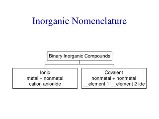
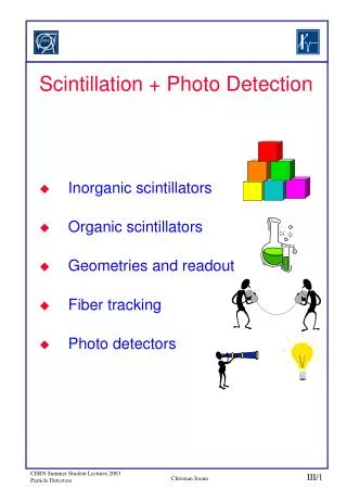
Inorganic Scintillators • Inorganic scintillators are inorganic materials (usually crystals) that emit light in response to ionizing radiation • NaI is the protypical example • Scintillation mechanism is different than for organic scintillators • Inorganic scintillators have higher Z and higher density (4-8 g/cm3 versus ~1 g/cm3) than organic scintillators • Higher Z and density translates into higher photon conversion efficiency and stopping power • Uses include calorimetry in particle physics, gamma ray spectroscopy, and medical/biological imaging
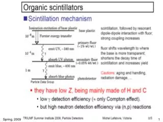
Inorganic Scintillators • The physical processes leading to scintillation in inorganic materials are complex and are dependent on the specific scintillator • A good picture to start with is that there is a core valence band and a conduction band • General steps to scintillation are • Initial electron-hole production and secondary production from the initial excitation energy • Thermalization • Transport and localization of electrons, holes, and excitons • Excitation and de-excitation of the luminescent centers
Inorganic Scintillators • Mechanism of luminescence in some inorganic scintillators
Inorganic Scintillators • Excitation/ionization • Causes the creation of (hot) electrons in the conduction band and (deep) holes in the inner core band • Relaxation • On a very short time scale (~1 fs), a large number of secondary electronic excitations occur • Radiative decay (secondary x-rays), Auger electrons, and inelastic electron-electron scattering
Inorganic Scintillators • Thermalization • Electrons and holes thermalize by making intraband transitions and by phonon production • Electrons end up at the bottom of the conduction band and holes end up at the top of the valence band • Occurs on ~ 1 ps time scale
Inorganic Scintillators • Transport/localization • Occurs on ~1-500 ns time scale • Electrons and/or holes migrate through the material and become trapped by impurities or activator ions, sometimes repeatedly, sometimes sequentially • Coulomb attraction can cause electrons and holes to form excitons or self-trapped excitons (STE) • Holes can become self-trapped (between two anions – called VK centers)
Inorganic Scintillators • Luminescence • During the localization stage, luminescent centers can be excited by various mechanisms and subsequently de-excite by the emission of scintillation light • Transport and forbidden transitions can be relatively slow • Two broad types of materials • Intrinsic or self-activated • Luminescence is produced by part of the crystal structure itself • External or activated • Must add some impurity to create energy levels between valence and conduction band
Inorganic Scintillators • Some examples
Inorganic Scintillators • Scintillation efficiency for 1 MeV photons
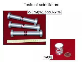
Inorganic Scintillators • NaI(Tl) • High light output and widely used in gamma spectroscopy • BaF2 • Fastest known inorganic scintillator • BGO (Bi4Ge3O12) • Used in x-ray tomography and PET • LSO (Lu2O3-SiO2(Ce)) • Used in PET • PbWO4 • High density and radiation hard but low light yield • Used in CMS EM calorimeter
NaI(Tl) • Discovered by Hofstadter in 1948 but still a standard in gamma ray spectroscopy today • Activator is thallium (Tl) at 10-3 mole fraction • + Excellent light yield • + Relatively small non-linearity in energy response • - Hydroscopic (must be sealed) • - Damage from mechanical or thermal shock • - Slow (t ~ 230 ns (90%) and 0.15 s (10%))
NaI(Tl) • Tl+ is a well-known luminescent center because of its 5d106s2 configuration • Also the hole mobility is very small which increases the rise time of the luminescence • The excited states are P states which means the luminescence is spin-forbidden i.e. slow decay • Because fluorescence occurs through the activator sites in the forbidden band, NaI will be transparent to scintillation light • Very efficient transfer to activator sites results in high light output • 38k photons per MeV of energy deposited
NaI(Tl) • The band structure for NaI (Tl) looks something like
NaI(Tl) • In NaI, here are some of the trapping mechansims • And here are SOME of the recombination mechanisms
NaI(Tl) • Light output is well-matched to a PMT
CsI(Tl) • CsI(Tl) needles used in digital radiography
BaF2 • An example of intrinsic emission • The very fast transitions in BaF2 and CsF are due to an intermediate transition between the valence and core bands • Actually there are two components of light: one with t ~ 0.6 ns and one with t ~ 630 ns
BGO • Bismuth germanate (Bi4Ge3O12) • + High density (7.13g/cm3) and high Z (83) result in high probability for photoelectric absorption • + Rugged and not hydroscopic • + No afterglow (phosphorescence) • - t ~ 300 ns (90%) and 60 ns (10%) • - Lower light yield (about 10-20% of NaI) • Finds widespread application in PET and CT scanners
BGO • Another example of intrinsic emission • In this case the luminescence center is one of the constituents of the crystal • Ionization of Bi results in a hole in the 6s2 level and an excited electron in the 6s6p level of Bi3+ • Can also be interpreted as trapped exciton deexcitation • BGO emission is well-matched to sensitivity of photodiodes
LSO • Lutetium Oxyorthosilicate (Lu2O3-SiO2(Ce)) • +Good light output (~75% of NaI) • +Relatively fast (t~47ns) • +High density (7.4g/cm3) • +Easily grown • -Contains 176Lu which is radioactive! • -Nonlinear response somewhat degrades energy resolution • Finds application in PET scanners
Inorganic Scintillators • Light output is strongly dependant on temperature
Inorganic Scintillators • Properties
Inorganic Scintillators • Properties
Inorganic Scintillators • Inorganic scintillators have found wide application in HEP as calorimeters as they provide excellent energy resolution • Crystal Ball – NaI • L3, CLEO, KTeV, BaBar, BELLE – CsI • CMS, ALICE - PWO • R&D on inorganic scintillators has been spurred in part by HEP (but medical imaging is the primary driver)
Inorganic Scintillators • Still an active area of R&D
Gamma Camera • These images are made using gamma cameras • We will cover the details of these (and similar detectors) in upcoming lectures
Gamma Camera • A schematic of a standard gamma camera
CMS EM Calorimeter • 80,000 PWO crystals
Standard Model Massive Higgs Boson • Summary Higgs Mechanism Local Gauge Invariance Massive Gauge Bosons
CMS EM Calorimeter • PWO is relatively radiation hard for HEP
SPECT • Single Photon Emission Computed Tomography • Diagnostic technique in nuclear medicine utilizing many of the concepts we have covered to date • SPECT differs from PET in that only one photon is detected • Topographic techniques are used to locate the source of emission
Gamma Camera • These images are made using gamma cameras • We will cover the details of these (and similar detectors) in upcoming lectures
Gamma Camera • A schematic of a standard gamma camera