Download
1 / 24
240 likes | 403 Views
CSC 250. Introduction to Networking Fundamentals Class Meeting 10. Chapter 4 roadmap. 4.1 Introduction and Network Service Models 4.2 Routing Principles 4.3 Hierarchical Routing 4.4 The Internet (IP) Protocol 4.5 Routing in the Internet 4.6 What’s Inside a Router? 4.7 IPv6

E N D
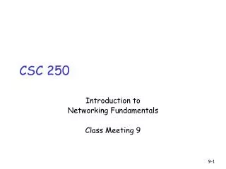
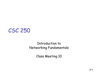
CSC 250 Introduction to Networking Fundamentals Class Meeting 10
Chapter 4 roadmap 4.1 Introduction and Network Service Models 4.2 Routing Principles 4.3 Hierarchical Routing 4.4 The Internet (IP) Protocol 4.5 Routing in the Internet 4.6 What’s Inside a Router? 4.7 IPv6 4.8 Multicast Routing 4.9 Mobility
Router Architecture Overview Two key router functions: • run routing algorithms/protocol (RIP, OSPF, BGP) • switching datagrams from incoming to outgoing link
Input Port Functions Decentralized switching: • given datagram dest., lookup output port using routing table in input port memory • goal: complete input port processing at ‘line speed’ • queuing: if datagrams arrive faster than forwarding rate into switch fabric Physical layer: bit-level reception Data link layer: e.g., Ethernet see chapter 5
Input Port Queuing • Fabric slower that input ports combined -> queueing may occur at input queues • Head-of-the-Line (HOL) blocking: queued datagram at front of queue prevents others in queue from moving forward • queueing delay and loss due to input buffer overflow!
Memory Input Port Output Port System Bus Switching Via Memory First generation routers: • packet copied by system’s (single) CPU • speed limited by memory bandwidth (2 bus crossings per datagram) Modern routers: • input port processor performs lookup, copy into memory • Cisco Catalyst 8500
Switching Via a Bus • datagram from input port memory to output port memory via a shared bus • bus contention: switching speed limited by bus bandwidth • 1 Gbps bus, Cisco 1900: sufficient speed for access and enterprise routers (not regional or backbone)
Switching Via An Interconnection Network • overcome bus bandwidth limitations • Banyan networks, other interconnection nets initially developed to connect processors in multiprocessor • Advanced design: fragmenting datagram into fixed length cells, switch cells through the fabric. • Cisco 12000: switches Gbps through the interconnection network
Output Ports • Buffering required when datagrams arrive from fabric faster than the transmission rate • Scheduling discipline chooses among queued datagrams for transmission
Output port queueing • buffering when arrival rate via switch exceeds output line speed • queueing (delay) and loss due to output port buffer overflow!
Our goals: understand principles behind data link layer services: error detection, correction sharing a broadcast channel: multiple access link layer addressing reliable data transfer, flow control: done! instantiation and implementation of various link layer technologies Chapter 5: The Data Link Layer
5.1 Introduction and services 5.2 Error detection and correction 5.3Multiple access protocols 5.4 LAN addresses and ARP 5.5 Ethernet 5.6 Hubs, bridges, and switches 5.7 Wireless links and LANs 5.8 PPP 5.9 ATM 5.10 Frame Relay Chapter 5 outline
Some terminology: hosts and routers are nodes (bridges and switches too) communication channels that connect adjacent nodes along communication path are links wired links wireless links LANs 2-PDU is a frame,encapsulates datagram “link” Link Layer: Introduction data-link layer has responsibility of transferring datagram from one node to adjacent node over a link
Datagram transferred by different link protocols over different links: e.g., Ethernet on first link, frame relay on intermediate links, 802.11 on last link Each link protocol provides different services e.g., may or may not provide rdt over link transportation analogy trip from Princeton to Lausanne limo: Princeton to JFK plane: JFK to Geneva train: Geneva to Lausanne tourist = datagram transport segment = communication link transportation mode = link layer protocol travel agent = routing algorithm Link layer: context
Link Layer Services • Framing, link access: • encapsulate datagram into frame, adding header, trailer • channel access if shared medium • ‘physical addresses’ used in frame headers to identify source, dest • different from IP address! • Reliable delivery between adjacent nodes • we learned how to do this already (chapter 3)! • seldom used on low bit error link (fiber, some twisted pair) • wireless links: high error rates • Q: why both link-level and end-end reliability?
Link Layer Services (more) • Flow Control: • pacing between adjacent sending and receiving nodes • Error Detection: • errors caused by signal attenuation, noise. • receiver detects presence of errors: • signals sender for retransmission or drops frame • Error Correction: • receiver identifies and corrects bit error(s) without resorting to retransmission • Half-duplex and full-duplex • with half duplex, nodes at both ends of link can transmit, but not at same time
link layer implemented in “adaptor” (aka NIC) Ethernet card, PCMCI card, 802.11 card sending side: encapsulates datagram in a frame adds error checking bits, rdt, flow control, etc. receiving side looks for errors, rdt, flow control, etc extracts datagram, passes to rcving node adapter is semi-autonomous link & physical layers frame frame Adaptors Communicating datagram rcving node link layer protocol sending node adapter adapter
5.1 Introduction and services 5.2 Error detection and correction 5.3Multiple access protocols 5.4 LAN addresses and ARP 5.5 Ethernet 5.6 Hubs, bridges, and switches 5.7 Wireless links and LANs 5.8 PPP 5.9 ATM 5.10 Frame Relay Chapter 5 outline
Error Detection • EDC= Error Detection and Correction bits (redundancy) • D = Data protected by error checking, may include header fields • Error detection not 100% reliable! • protocol may miss some errors, but rarely • larger EDC field yields better detection and correction
Parity Checking Two Dimensional Bit Parity: Detect and correct single bit errors Single Bit Parity: Detect single bit errors 0 0
Sender: treat segment contents as sequence of 16-bit integers checksum: addition (1’s complement sum) of segment contents sender puts checksum value into UDP checksum field Receiver: compute checksum of received segment check if computed checksum equals checksum field value: NO - error detected YES - no error detected. But maybe errors nonetheless? More later …. Internet checksum Goal: detect “errors” (e.g., flipped bits) in transmitted segment (note: used at transport layer only)
Checksumming: Cyclic Redundancy Check • view data bits, D, as a binary number • choose r+1 bit pattern (generator), G • goal: choose r CRC bits, R, such that • <D,R> exactly divisible by G (modulo 2) • receiver knows G, divides <D,R> by G. If non-zero remainder: error detected! • can detect all burst errors less than r+1 bits • widely used in practice (ATM, HDCL)
CRC Example Want: D.2r XOR R = nG equivalently: D.2r = nG XOR R equivalently: if we divide D.2r by G, want remainder R D.2r G R = remainder[ ]