Download
1 / 23
240 likes | 425 Views
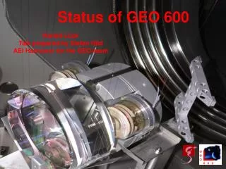
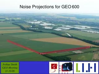
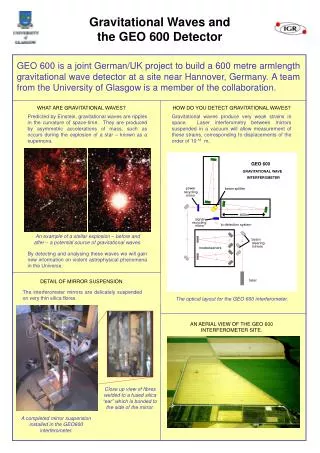
The GEO 600 Detector. Andreas Freise and the GEO 600 Team University of Hannover May 20, 2002. GEO. LIGO. VIRGO. TAMA. ACIGA. Location of GEO 600. the gallery in the central building. the clean room. t he cen t ral area. North Arm 600 m. the trench with vacuum tube. East Arm

E N D
The GEO 600 Detector Andreas Freise and the GEO 600 Team University of Hannover May 20, 2002
GEO LIGO VIRGO TAMA ACIGA Location of GEO 600
the gallery in the central building the clean room the central area North Arm 600 m the trench with vacuum tube East Arm 600 m
Michelson Interferometer with Dual-Recycling Mode Cleaners folded arms with an optical path length of 2400 m Laser triangular 8 m ring cavities 14 W Output Mode Cleaner triangular 0.1 m ring cavity GEO 600 - optical layout
Michelson Interferometer Mode Cleaners Laser Output Mode Cleaner Vacuum Enclosure • 400 m3 volume /4000 m2 surface • 600 m long tubes, 60 cm diameter • 2 m tall tanks with 1m diameter • tubes : 110-8 mbar • main tanks : 510-8 mbar
The mechanical structure inside vacuum tanks is mounted on three Stacks: Triple Pendulum Suspension Seismic Isolation
Monolithic Suspension Weld Silicate (Hydroxy- Catalysis) Bonding
final optics test optics Status May 2002 (I) Michelson Interferometer Mode Cleaners Laser • Laser + Mode Cleaners complete • Power-Recycled Michelson with low finesse • two main mirrors with monolythic suspension
enter vacuumsystem Slave Slave Master Master Laser System • Master Laser: • Nd:YAG • NPRO (non-planar ring oscillator) • 800mW @ 1064 nm • Slave Laser: • Nd:YAG • injection locked ring cavity • 14 W @ 1064nm • less than 5% in higher modes
10 kW at Beam Splitter Light Power Michelson Interferometer Mode Cleaners Laser ~ 5 kW 5 W 10 W 1 W Output Mode Cleaner ~ 50 mW
final optics test optics Status May 2002 (II) Michelson Interferometer Mode Cleaners 200 W at Beam Splitter Laser 2 W 1 W MPR Power-Recycled Michelson: MPR T=1.5% Gain 200 Contrast 4000 Mode Cleaners: Troughput 80% 72% Finesse 2700 1900 Visibility 91% 92% ~ 50 mW
controlled by distributed LabView virtual instruments (digital bus, read ~1000 control channels, lock automation) supervised by digital electronic (digital potentiometers, CMOSswitches, mico-controller, AD converter) control loops made of analog electronics Automated Control • Three types of control tasks: • Local control: damping of pendulum resonances, active seismic isolation, temperature control • Global control of longitudinal degrees of freedom of optical systems: length and frequency stabilisation • Global control of alignment of optical components: Automatic alignment system
Laser Frequency Stabilisation: • no rigid reference cavity • laser is directly stabilised to suspended cavities • 3 sequential Pound- Drever-Hall control loops • common mode of the power-recycled Michelson serves as frequency reference Length and Frequency Control Mode Cleaners 25 MHz Michelson Interferometer 13 MHz 37 MHz Laser the now pre-stabilised laser frequency is locked to the common mode of the power-recycled Michelson interferometer the length of the first mode cleaner is locked to the length of the second the laser frequency is locked to the length of the first mode cleaner Output Mode Cleaner
Frequency Noise Required frequency stability at the input of thefinal interferometer: 10 Hz/sqrt(Hz)
Differential arm length: • (gravitational wave signal) • heterodyne detection • Schnupp modulation Michelson Length Control Mode Cleaners Michelson Interferometer 15 MHz Laser 10 MHz • Signal recycling control: • a separate modulation • frequency • reflected beam from AR coating Output Mode Cleaner
Test Mass Actuators • Reaction Pendulum: • 3 coil-magnet actuators at intermediate mass • Electrostatic actuation on test mass
Alignment Control (I) DC: beam positions are defined by reference marks, spot position control, below 0.1 Hz around the resonance frequencies of the suspension pendulums the beam follows the input beam from the laser bench, differential wave-front sensing, 0.1 Hz to 10 Hz no active control at the expected signal frequencies, the two mode cleaners suppress geometry fluctuations by ~106
+2 for MI differential mode +2 for signal recycling 16 spot position control Alignment Control (II) 4 degrees of freedom for MC 1 +4 for MC 2 +4 for MI common mode + 32 = 48 Status May 2002: Complete (except for the not yet installed signal recycling mirror) differential wave-front sensing
Data Acquisition Data acquisition uses 3 Data Collecting Units (DCUs) with (in total) : 64 channels @ 16384 Hz 64 channels @ 512 Hz ~ 1000 channels @ 1Hz Possible data rate: 600kB/sec ~ 50 GB/day
Daily overall duty cycles, maintenance periods not subtracted Coincidence Run with LIGO • Engineering run 28.12.2001 - 14.01.2002 • 430 hours of continous data taking • Duty cycle (> 10mins) ~ 75% • 98% for the last 24h. • Longest lock: 3h:38min • ~ 0.9 TB of data recorded
Automated Control Laser-mode-cleaner system with longitudinal control and auto alignment runs continuously since December 2000 Total time for relocking the injection locked laser and the two mode cleaners is typically < 40 sec Continuous lock of the auto-aligned mode cleaner system: 48 hours Locked 1200 m cavity without any re-alignment of the cavity mirrors for 36 hours Continuous lock of the entire system: 10 hours