Download
1 / 28
300 likes | 585 Views
CHE 185 – PROCESS CONTROL AND DYNAMICS. PID CHARACTERISTICS AND SIGNAL FILTERING. DIGITAL VERSIONS OF THE PID ALGORITHM. CONTROLLER ACTION - DIRECT AND REVERSE A COMBINATION OF PROCESS GAIN AND THE TYPE OF ACTUATOR USED. PROCESS GAIN IS A PROCESS CHARACTERISTIC. WHEN PROCESS GAIN IS NEGATIVE:

E N D
CHE 185 – PROCESS CONTROL AND DYNAMICS PID CHARACTERISTICS AND SIGNAL FILTERING
DIGITAL VERSIONS OF THE PID ALGORITHM • CONTROLLER ACTION - DIRECT AND REVERSE • A COMBINATION OF PROCESS GAIN AND THE TYPE OF ACTUATOR USED. PROCESS GAIN IS A PROCESS CHARACTERISTIC. • WHEN PROCESS GAIN IS NEGATIVE: • THERE IS A DECREASE IN THE VALUE OF THE CONTROLLED VARIABLE WITH AN INCREASE IN THE CONTROLLED PROPERTY
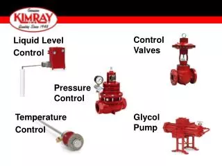
Direct Level Control Example • Process gain is positive because when flow in is increased, the level increases. • If the final control element is direct acting, use reverse acting PID. • For reverse acting final control element, use direct acting PID
reverse Level Control Example • Process gain is negative because when flow out is increased, the level decreases. • If the final control element is direct acting, use direct acting PID. • For reverse acting final control element, use reverse acting PID.
ACTUATOR DIRECTION • BASED ON PROCESS NEEDS • DIRECT ACTING ACTUATORS INCREASE VALUES OF THE FINAL CONTROL ELEMENT WITH INCREASES IN DRIVING FORCE. A DIRECT ACTING ACTUATOR ON A VALVE (AIR-TO-OPEN OR NORMAL CLOSED) INCREASES THE OPENING WITH INCREASING AIR PRESSURE. • REVERSE ACTING ACTUATORS DECREASE VALUES OF THE FINAL CONTROL ELEMENT WITH INCREASES IN DRIVING FORCE. A REVERSE ACTING ACTUATOR ON A VALVE (AIR-TO-CLOSE OR NORMAL OPEN) DECREASES THE OPENING WITH INCREASING AIR PRESSURE
Proportional Band • Another way to express the controller gain. • Kc in this formula is dimensionless. That is, the controller output is scaled 0-100% and the error from setpoint is scaled 0-100%. • In more frequent use 10-15 years ago, but it still appears as an option on DCS’s.
Conversion from PB to Kc • Proportional band is equal to 200%. • The range of the error from setpoint is 200 psi. • The controller output range is 0 to 100%.
Conversion from Kc to PB • Controller gain is equal to 15 %/ºF • The range of the error from setpoint is 25 ºF. • The controller output range is 0 to 100%.
Derivation of the Velocity Form of the PID Control Algorithm • SEE SECTION 7.5
Velocity Form of DERIVATIVE FROM ERROR FOR PID Controller • Note the difference in proportional, integral, and derivative terms from the position form. • Velocity form is the form implemented on DISTRIBUTED CONTROL SYSTEMS.
Correction for Derivative Kick • Derivative kick occurs when a setpoint change is applied that causes a spike in the derivative of the error from setpoint. • Derivative kick can be eliminated by replacing the approximation of the derivative based on the error from setpoint with the negative of the approximation of the derivative based on the measured value of the controlled variable, i.e.,
Correction for Aggressive Setpoint Tracking • For certain process, tuning the controller for good disturbance rejection performance results in excessively aggressive action for setpoint changes. • This problem can be corrected by removing the setpoint from the proportional term. Then setpoint tracking is accomplished by integral action only. • SEE EQN 7.5.5
SUMMARY OF 3 Versions of the PID Algorithm Offered on DCS’s • (1) The original form in which the proportional, integral, and derivative terms are based on the error from setpoint • EQN. 7.5.4
SUMMARY OF 3 Versions of the PID Algorithm Offered on DCS’s • (2) The form in which the proportional and integral terms are based on the error from setpoint while the derivative-on-measurement is used for the derivative term • EQN. 7.5.2
SUMMARY OF 3 Versions of the PID Algorithm Offered on DCS’s • (3) The form in which the proportional and derivative terms are based on the process measurement and the integral is based on the error from setpoint. • EQN. 7.5.5
SIGNAL FILTERING • FILTERS ARE USED TO REMOVE SOME OF THE NOISE FROM LOOPS AND OPERATE WITH AVERAGED VALUES FOR VARIABLES. • THE SIMPLEST FILTERS AVERAGE n PREVIOUS VALUES TO OBTAIN THE ONE ACTUALLY SENT TO THE CONTROLER. • FILTERS ARE LOCATED AFTER THE SENSOR SIGNAL IN THE BLOCK DIAGRAM
Filtering the Process Measurement • Filtering reduces the effect of sensor noise by approximating a running average. • Filtering adds lag when the filtered measurement is used for control. • Normally, use the minimum amount of filtering necessary. • f- filter factor (0-1)
FILTERING EXAMPLE USING 50 DATA POINTS • INITIAL DATA ARE SHOWN AS OUTPUT
FILTERING EXAMPLE USING 50 DATA POINTS • FILTERED DATA ARE AVERAGED VALUES FOR THE PREVIOUS 5 DATA POINTS • CUMULATIVE VALUES ARE THE AVERAGES STARTING FROM THE FIRST POINT. • RESULTING GRAPH (NEXT PAGE) SHOWS SIGNAL SENT TO COMPARATOR • ALSO SEE FIGURE 7.8.1
FILTERING EXAMPLE USING 50 DATA POINTS • THE BALANCE REQUIRED IS TO MINIMIZE THE NOISE SO A RELATIVELY STABLE SIGNAL CAN BE SENT TO THE CONTROLLER. • TOO FEW DATA POINTS IN THE AVERAGE LEAVES A RESIDUAL THAT CAN HAMPER CONTROL • TOO MANY DATA POINTS RESULTS IN VALUES THAT CAN LAG THE ACTUAL VALUES • DERIVATIVE ACTION IS THE PROPERTY THAT IS MOST AFFECTED BY NOISE
Analysis of Example • τf is equal to Δt (1/f-1) as f becomes small, τfbecomes large. • As τf is increased, τpwill increase. • Critical issue is relative magnitude of τf compare to τp.
Filter Factor (f), the Resulting Repeatability Reduction Ratio (R) and the Filter Time Constant (τf)
Key Issues for Sensor Filtering • To reduce the effect of noise (i.e., R is increased), f must be reduced, which increases the value of τf. Filtering slows the closed-loop response significantly as tf becomes larger than 10% of τp. • The effect of filtering on the closed-loop response can be reduced by increasing the frequency with which the filter is applied, i.e., reducing Δtf.


![Seven Quality Tools [Statistical Process Control]](https://cdn3.slideserve.com/6416179/seven-quality-tools-statistical-process-control-dt.jpg)