Download
1 / 48
1.24k likes | 3.59k Views
Electrical and optical properties of thin films. sami.franssila@tkk.fi. Outline. Metallic films Thickness dependent resistivity Limit of Ohm’s law Metallization for flexible electronics Semiconducting films (Silicon microtechnology 2009 slides !) Dielectric films, electrical properties

E N D
Electrical and optical properties of thin films sami.franssila@tkk.fi
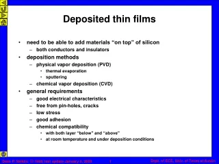
Outline • Metallic films • Thickness dependent resistivity • Limit of Ohm’s law • Metallization for flexible electronics • Semiconducting films (Silicon microtechnology 2009 slides !) • Dielectric films, electrical properties • Dielectric films, optical properties
Resistivity ρ = ρresidual + ρtemp Linear TCR above Debye temperature (typically 200-400K) Murarka: Metallization
Resistivity: impurity effects Murarka
Resistivity: alloying effects Murarka
Alloying (2) Zirconium at grain boundaries acts as an extra barrier, preventing formation of high resistivity Cu3Si
Annealing defects away Annealing defects at elevated temperature lowers resistance (no reaction with underlying film/substrate) Murarka: Metallization
Thin film reaction: Co+Si Murarka
Resistivity as a function of film thickness γ= film thickness/mean free path Mean free paths typically tens of nanometers at RT Murarka
Resistivity in polycrystalline films R = reflectivity at grain boundaries (0.17 for Al, 0.24 for copper) lo = mean free path inside grain d = spacing between reflecting planes Grain boundaries trap impurities, and above solubility limit, this leads to segregation Murarka
Resistivity depends on patterns! You cannot calculate thickness from resistance R = ρL/Wt because thin film resistivity ρ is linewidth and thickness dependent (use e.g. X-rays to get an independent thickness value) G.B. Alers, J. Sukamto, S. Park, G. Harm and J. Reid, Novellus Systems, San Jose -- Semiconductor International, 5/1/2006
Grain size affected by: -underlying film (chemistry and texture) -deposition process (sputtering vs. plating; & plating A vs. plating B) -material purity -thermal treatments -geometry of structures on wafer G.B. Alers, J. Sukamto, S. Park, G. Harm and J. Reid, Novellus Systems, San Jose -- Semiconductor International, 5/1/2006
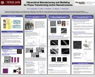
PDMS casting Seed metal, lithography and electroplating Seed metal, lithography and electroplating Resist removal, PDMS casting Resist removal and DRIE DRIE Brute force metallization of an elastic polymer membrane: Sputtering+ electroplating on polymer Anchored metallization by metallization of silicon followed by polymer casting Yin, H-L et. al.: A novel electromagnetic elastomer membrane actuator with a semi-embedded coil, Sensors and Actuators A 139 (2007), pp. 194–202.
Electromigration Electromigration is metal movement due to electron momentum transfer. Electrons dislodge metal atoms from the lattice, and these atoms will consequently move and accumulate at the positive end of the conductor and leave voids at the negative end.
Stability of metallization Ti and Ti/TiN barriers To prevent reaction between Si and Cu
Specific contact resistance, rc Ti reduces any SiO2 at the interface to TiO rc down TiN is high resistivity material higher rc CuTi starts to form above 300oC TiN is a better barrier and rc is reduced the higher the anneal temperature
Semiconductor films • LPCVD polysilicon • In-situ vs. Ex-situ • α-Si vs. true poly • α-Si (annealing, crystallization)
Dielectric films: electrical • Dielectric constant • Breakdown field • Structure vs. Stability vs. Leakage
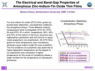
High-k dielectrics Amorphous initially, polycrystalline as thickness increases
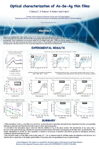
Optical thin films The technique must allow good control and reproducibility of the complex refractive index k (λ) < 10-4 for transparent films Two materials with
Optical • Amorphous • Isotropic • No birefrongence • Losses below 10-4 required • Waveguide losses < 1 dB/cm
General requirements Mechanical scratch resistance Reflection Environmental stability Waveguiding requires large nhigh-nlow Transmission, absorption
General requirements (2) • Depositon rate • Uniformity, thickness <3%, even <1% • Uniformity, refractive index <0.001 • Stresses • Defect density
Smart windows • Layers correspond to (1) polyester-based • laminated double foil, (2) ITO transparent electrodes, (3) • nanoporous tungsten oxide, (4) polymer serving as a conductor • of ions, (5) nanoporous nickel oxide. The application of a • voltage (denoted as V) changes the transparency
Diamond as optical material pc-D (polycrystalline diamond) High transparency 200 nm ... 20 µm High refractive index, n = 2.35 Crystal size, ~ µm, leads to scattering at visible wavelengths >600oC deposition rules out many optical substrates DLC-films not transparent in visible but in IR yes nf ~ 1.6-2.2 k ~ up to 0.8 (heavy absorption)
SiOxNy:H Truely oxynitride, Si-O-N bonds, not SiO and SiN domains Amorphous and homogenous till 900oC Open pores lead to H2O adsorption and lower n Closed pores lead to density and nf reduction Excellent material for graded index filters: n=1.48-2.0 Reproducibility of n is ~1%
Optical filters (1) • Multilayer (step index) design • Inhomogenous graded index design • Quasi-inhomogenous design (λ/4 layers)
Optical filters (3) Refractive index profile On glass substrate On polycarbonate substrate Nitrous oxide flow rate